Pick Your Goldeye

SWIR cameras (short-wave infrared cameras) detect photons with wavelengths between 900 nm and 2500 nm. Short wave IR light interacts with objects similarly to visible light, as it is reflective; consequently, it exhibits shadows and contrasts in its imagery. As a result, images from SWIR cameras are comparable to visible images in terms of resolution and detail.
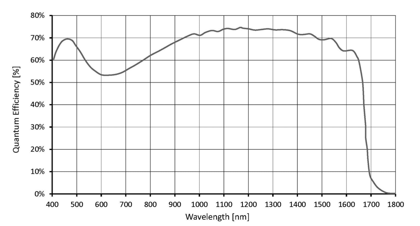
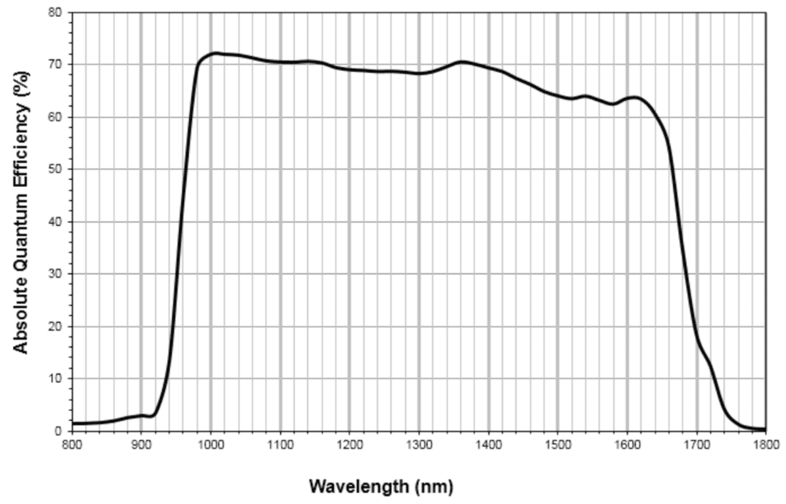
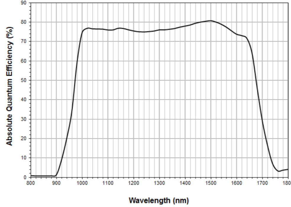
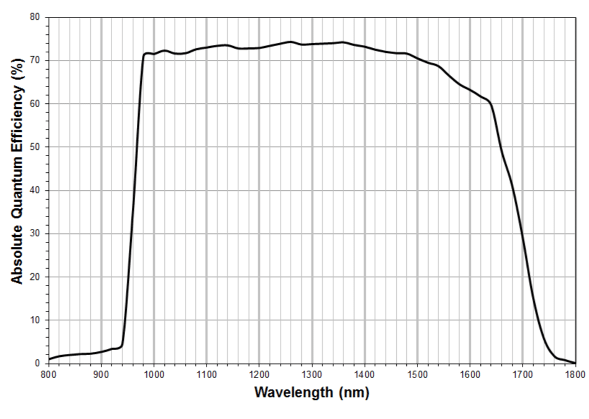
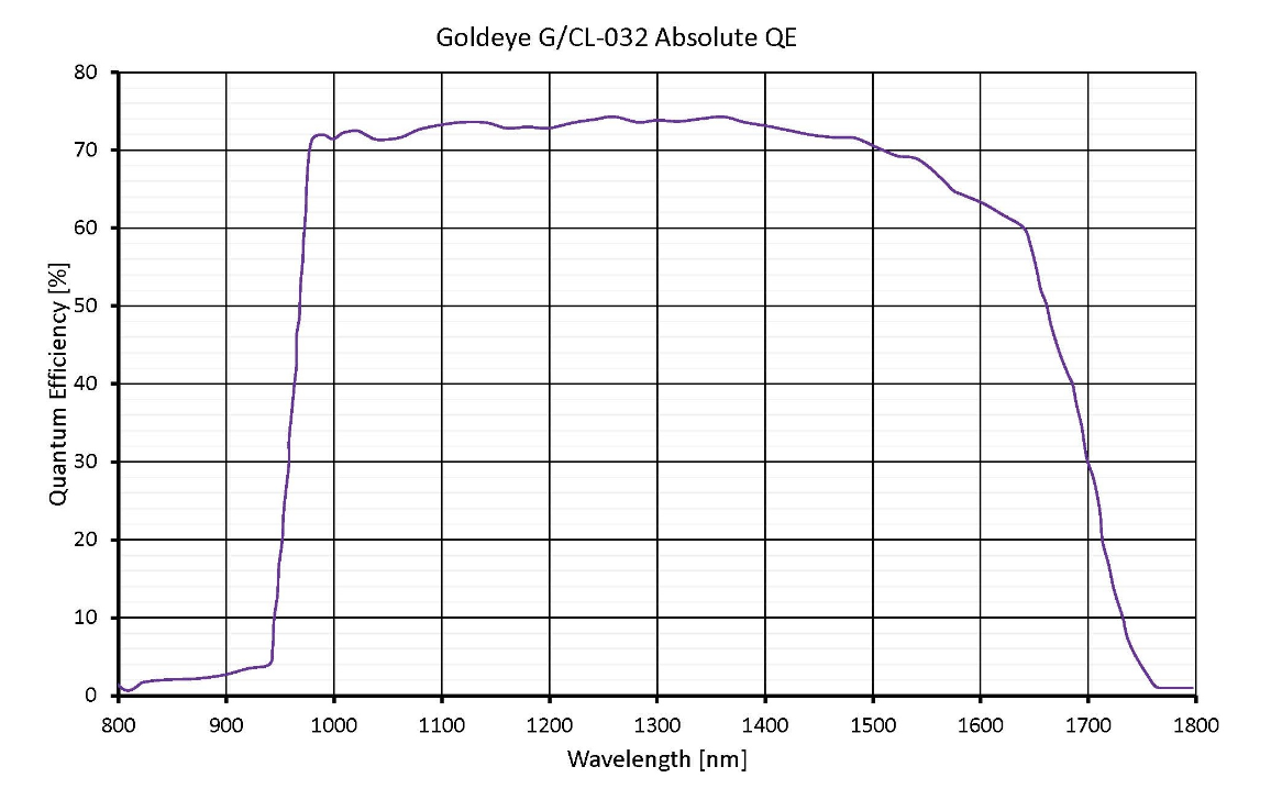
Because standard silicon-based sensors are typically sensitive up to 1000 nm only, SWIR cameras require sensors capable of imaging beyond the upper limit of silicon. InGaAs (indium gallium arsenide) sensors are conventionally used for SWIR imaging and cover the 900 nm to 1700 nm spectral range with high quantum efficiency (typically > 70%). Recent improvements to InGaAs sensors enable imaging both visible and SWIR (400 nm to 1700 nm using SenSWIR™ technology from Sony©, for example) or beyond the standard 1.7 µm cut-off with extended range solutions up to 2.2 µm.
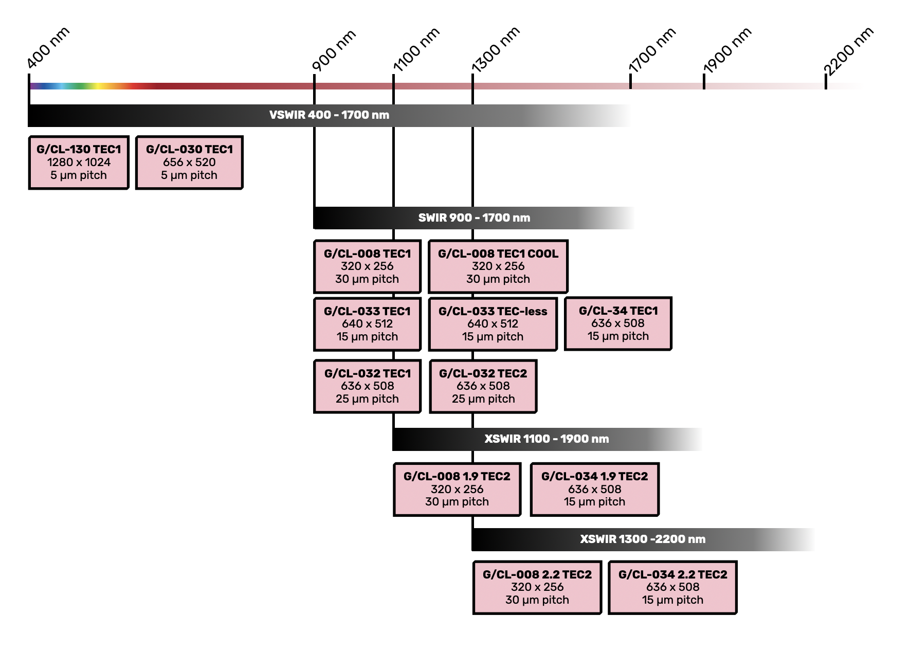
As such, 4 categories of Goldeye cameras are available:
- Goldeye VSWIR covering an extended spectral range from 400 to 1700 nm
- Goldeye SWIR covering a spectral range from 900 to 1700 nm
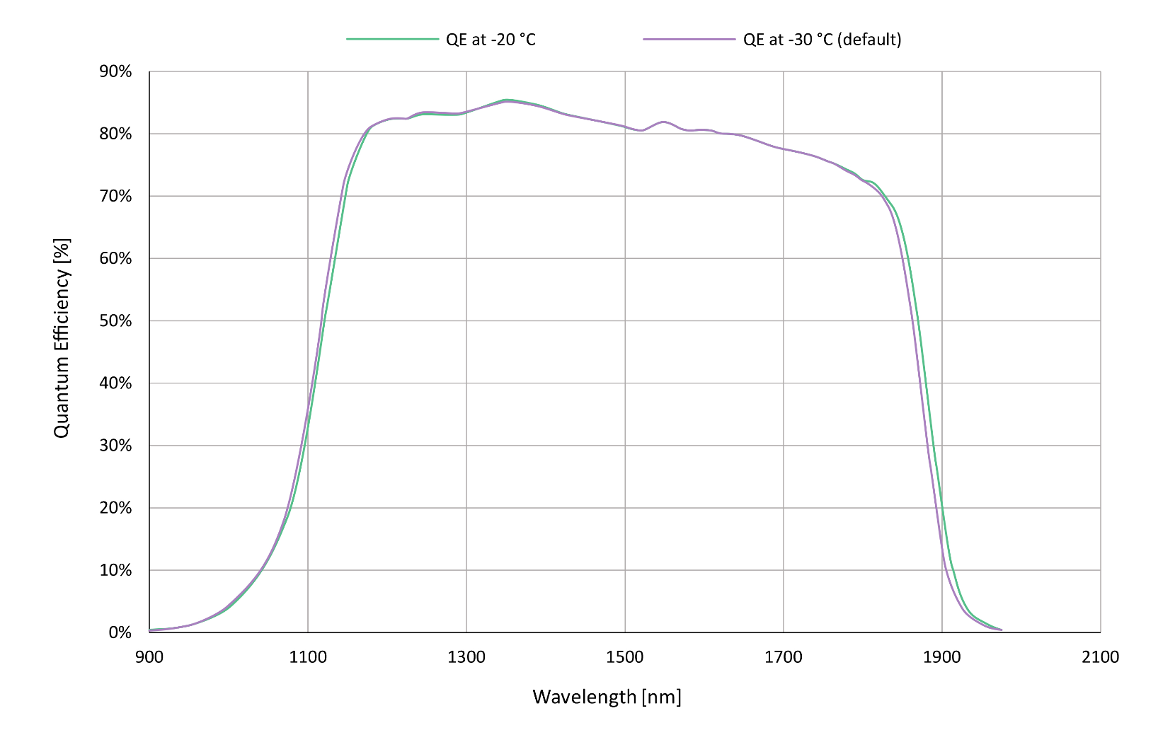
- Goldeye XSWIR 1.9 covering an extended spectral range from 1100 to 1900 nm
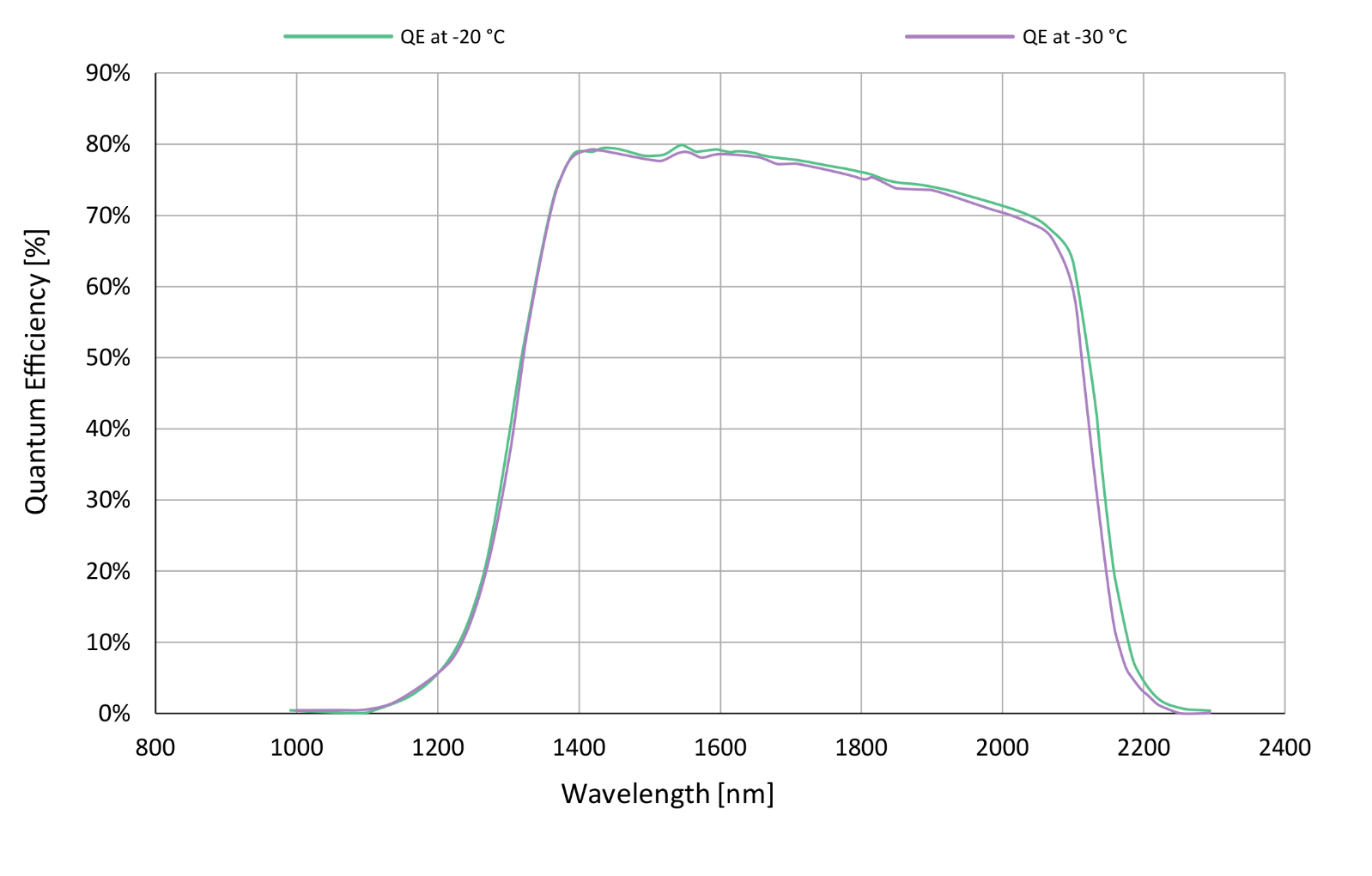
- Goldeye XSWIR 2.2 covering an extended spectral range from 1300 to 2200 nm
Resolution: 1280 x 1024 px – SXGA
Sony InGaAs IMX990
Pixel pitch: 5 µm
Cooling: TEC1
Max FPS: 94 Hz full frame
ADC: 12-bit
Readout noise: 210 e- (gain 1)
Resolution: 656 x 520 px – VGA
Sony InGaAs IMX991
Pixel pitch: 5 µm
Cooling: TEC1
Max FPS: 234 Hz full frame
ADC: 12-bit
Readout noise: 210 e- (gain 1)
Resolution: 320 x 256 px – QVGA
Pixel pitch: 30 µm
Cooling: TEC1
Max FPS: 344 Hz full frame
ADC: 14-bit
Readout noise: 210 e- (gain 1)
Resolution: 320 x 256 px – QVGA
Pixel pitch: 30 µm
Cooling: TEC1 + FAN
Max FPS: 344 Hz full frame
ADC: 14-bit
Readout noise: 210 e- (gain 1)
Resolution: 640 x 512 px – VGA
Pixel pitch: 15 µm
Cooling: TEC1
Max FPS: 301 Hz full frame
ADC: 14-bit
Readout noise: 32 e- (gain 2)
Resolution: 640 x 512 px – VGA
Pixel pitch: 15 µm
Cooling: TEC-less
Max FPS: 301 Hz full frame
ADC: 14-bit
Readout noise: 32 e- (gain 2)
Resolution: 640 x 512 px – VGA
Pixel pitch: 15 µm
Cooling: TEC-less
Max FPS: 303 Hz full frame
ADC: 14-bit
Readout noise: 32 e- (gain 2)
Resolution: 636 x 508 px – VGA
Pixel pitch: 25 µm
Cooling: TEC1
Max FPS: 100 Hz full frame
ADC: 14-bit
Readout noise: 170 e- (gain 1)
Resolution: 636 x 508 px – VGA
Pixel pitch: 25 µm
Cooling: TEC2
Max FPS: 100 Hz full frame
ADC: 14-bit
Readout noise: 170 e- (gain 1)
Resolution: 320 x 256 px – QVGA
Pixel pitch: 30 µm
Cooling: TEC2
Max FPS: 344 Hz full frame
ADC: 14-bit
Readout noise: 200 e- (gain 1)
Resolution: 636 x 508 px – VGA
Pixel pitch: 15 µm
Cooling: TEC2
Max FPS: 303 Hz full frame
ADC: 14-bit
Readout noise: 15 e- (gain 1)
Frame Rate
The frame rate is given in fps or Hz for a given sensor resolution and pixel format (or bit-depth). For all Goldeye cameras, windowing the sensor (also known as cropping, AOI etc) will result in an increased frame rate.
This is true for both X and Y directions except for the Godleye G/CL-130 and G/CL-030 for which only a reduction in number of rows will increase the FPS.
See table below showing the max fps in full frame for each model with different pixel formats.
Max FPS full frame - GigE Ethernet interface
Pixel Size
5 µm vs. 15 µm: does it really matter?
Small pixels have the advantage of offering higher pixel density, thus giving more details and potentially seeing shapes or patterns that would not be picked up by larger pixels. This is especially true for applications such as laser beam profiling where a laser beam directly hits the sensor surface or microscopy where a smaller pixel typically means resolving smaller objects/defects, provided the optics are adequate.
The pictures below compare the same laser beam (left image) and same wafer (right image) between a 15 µm-pitch and 5 µm-pitch InGaAs sensor.
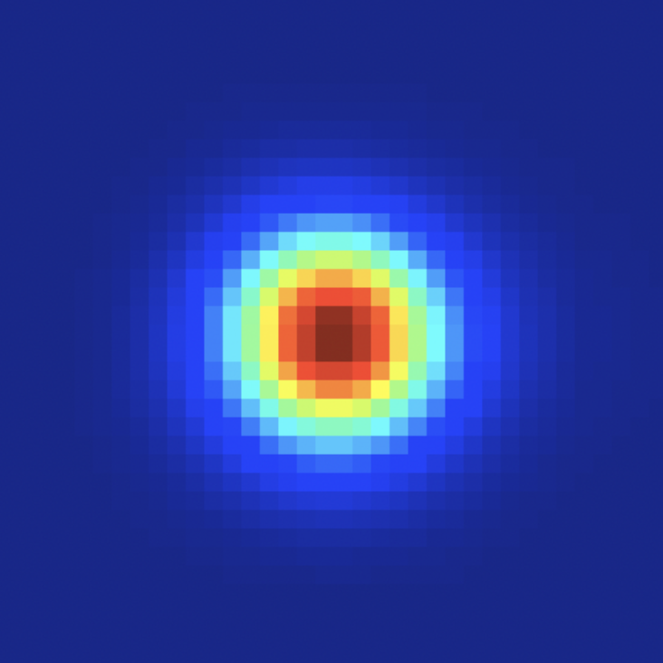
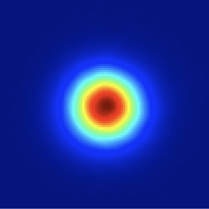

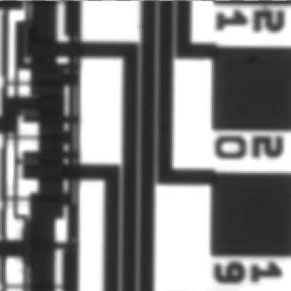
Depending on the application, a smaller pixel is not always desired as the amount of signal collected is proportional to the photosensitive area of the pixel. Therefore, with similar noise properties, a 15 µm pixel will collect 9 times more photons than a 5 µm would, thus providing a factor 4 in SNR.
Often times, the quantum efficiency of InGaAs sensors being high (>70% typically), a compromise needs to be found between pixel size and sensor noise when considering the signal to noise ratio.
Readout Noise
The readout noise (also referred as read noise or temporal noise) is the noise (in e-) generated by the sensor ROIC (Read Out Integrated Circuit) that converts the stored charge of each pixel into an analog voltage to be quantified (digitized) by the A/D converter. It may be viewed as a ‘toll’ that must be paid for reading the stored charge. It is independent of the sensor temperature.
The readout noise corresponds to the noise with short exposure times (theoretically zero). A low readout noise is desirable as it allows the camera to detect low light levels and attain a high dynamic range. This is especially true for applications with high frame rates (short exposure times) where the dark noise is typically negligible.
Goldeye TEC1 at a glance
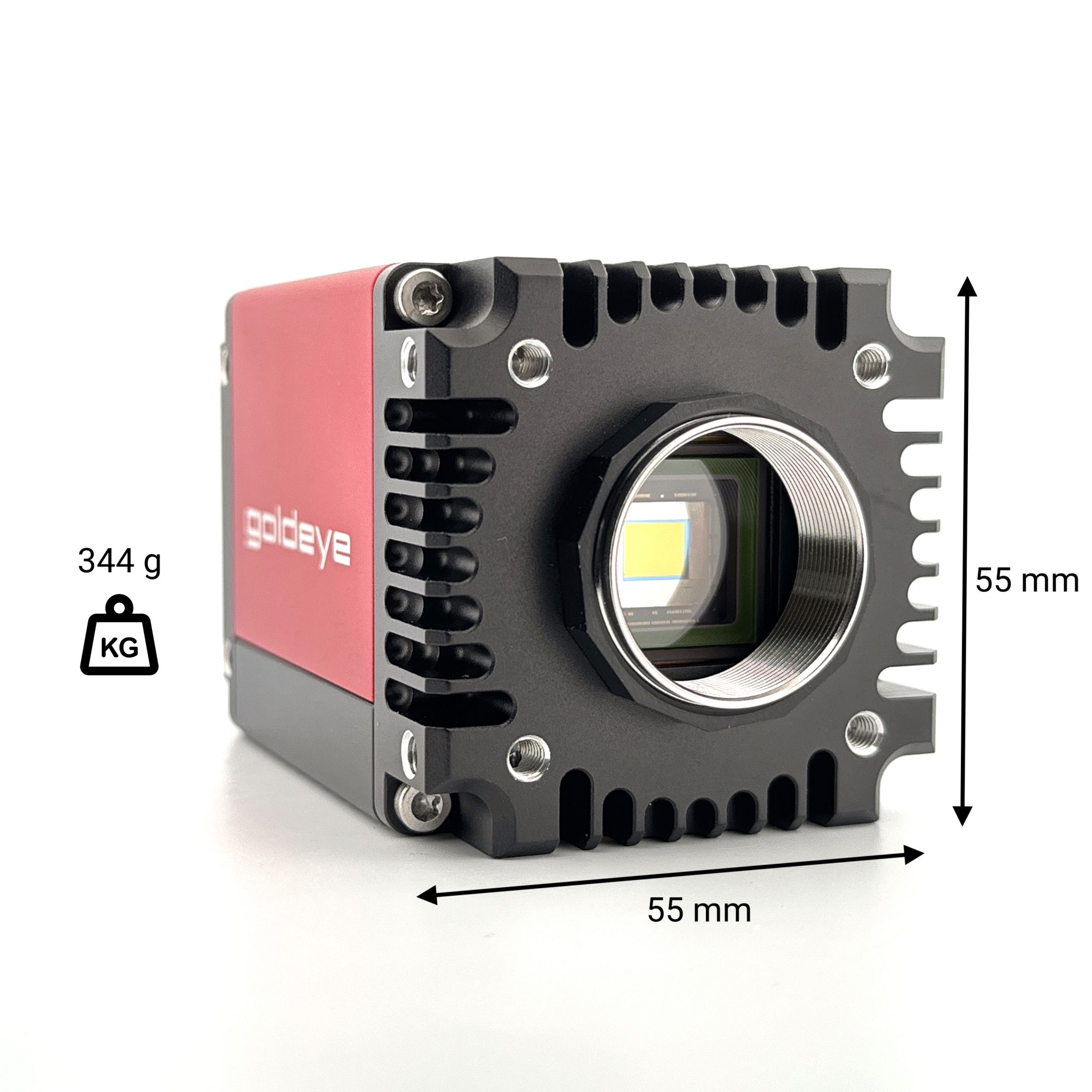
C-mount lens interface
M4 – 6↓ (4x) mounting holes
Sensor coverglass
(window-less option
on selected models)
Heat-dissipating
aluminum housing
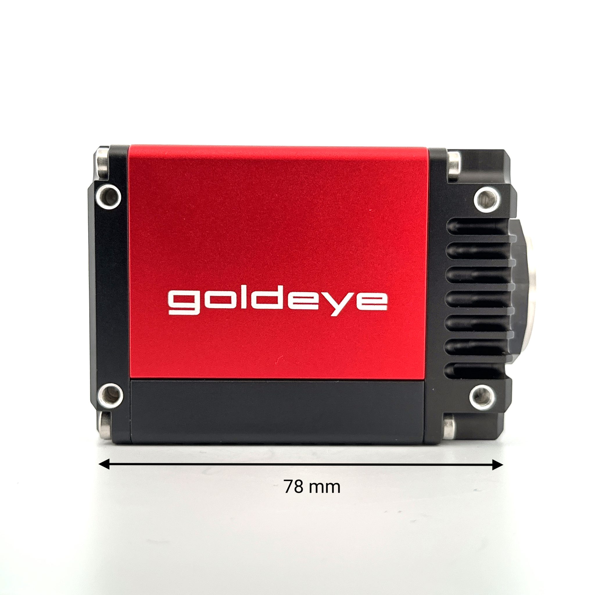
M4 – 6 (4x) mounting holes
On each side (top, bottom, left and right)
Can be used for heatsinks
Heat-dissipating
aluminum housing
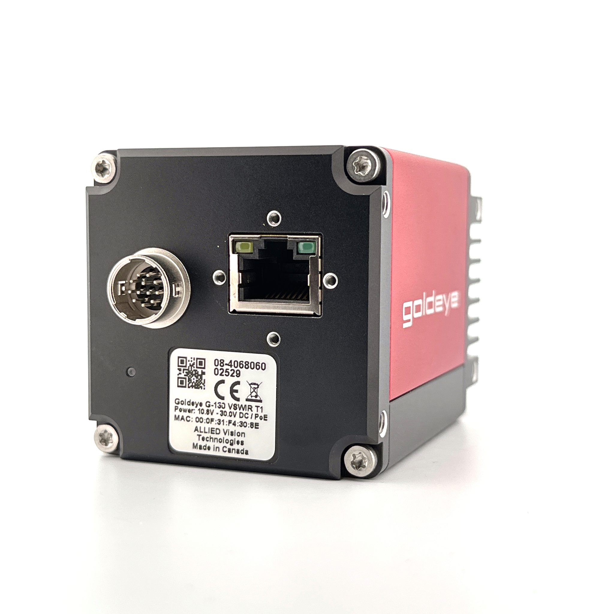
12-pin hirose
I/O connector + power supply
GigE Ethernet port (PoE)
with screw-locking
TE Cooling
LED Status
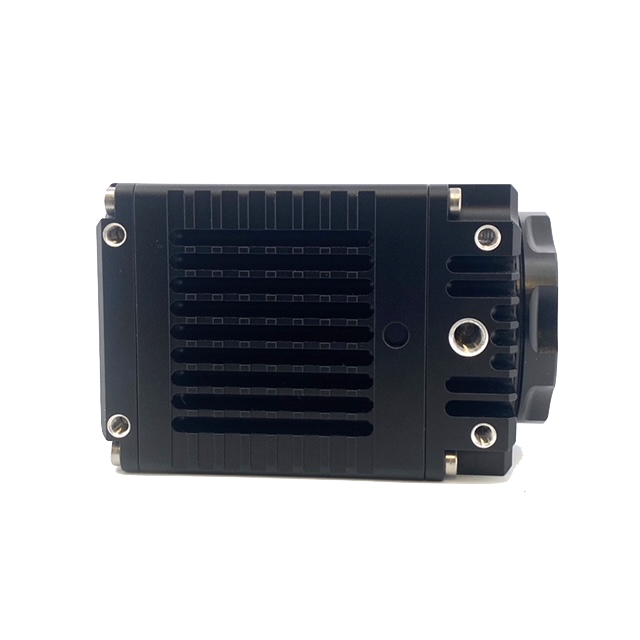
M4 -6↓ (x)
1/4-20
Tripod Mount
Ø4.5 – 1.5↓
| Operating temperature | Power requirements | Power consumption |
|---|---|---|
| -20 ºC to +55 ºC (housing) | 10.8 V DC to 30.0 V or via PoE | 10.8 W at 12 VDC; <12.95 W PoE |
Goldeye TEC1 Cool & TEC2 at a glance
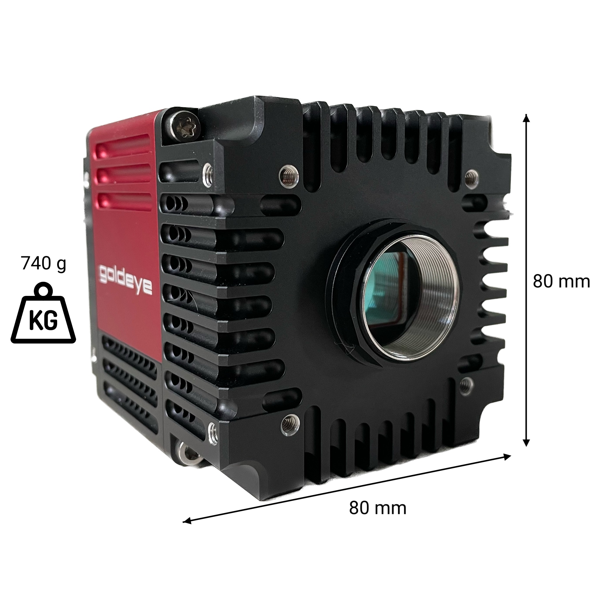
C-mount lens interface
M4 – 6↓ (4x) mounting holes
Vents for air-flow
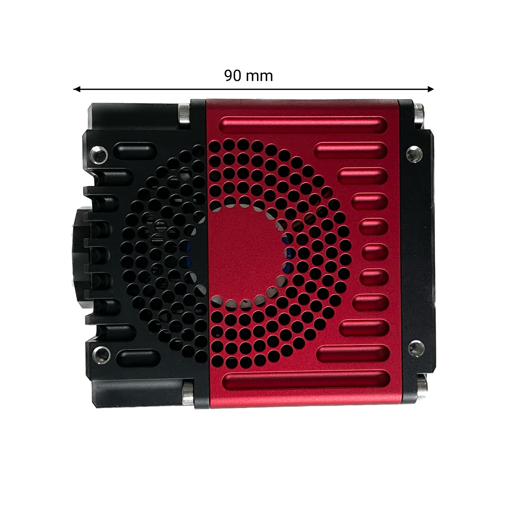
Fan + air flow
M4 – 6↓ (4x) mounting holes
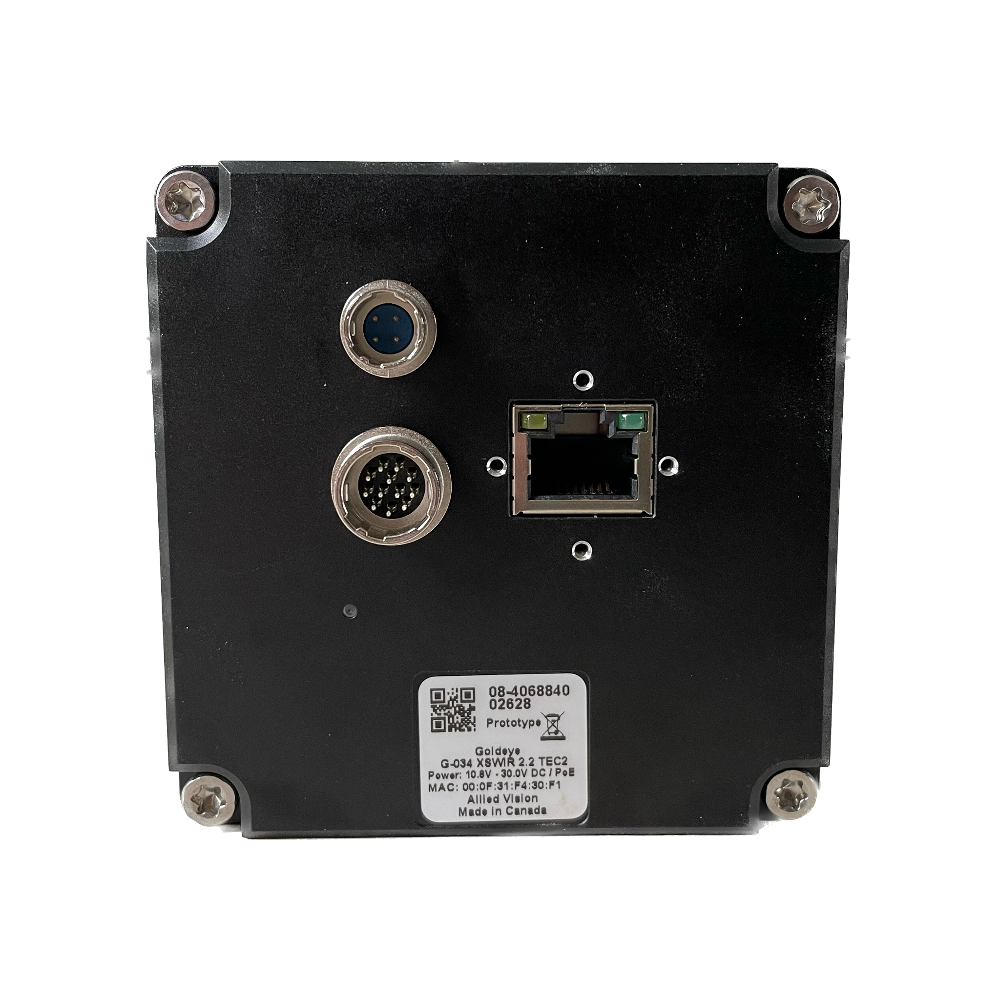
GigE Ethernet (PoE)
with locking screws holes
4-pin hirose connector
power supply only
12-pin hirose
I/O connector only
TE Cooling
LED Status
| Operating temperature | Power requirements |
|---|---|
| -20 ºC to +55 ºC (housing) | 10.8 V DC to 30.0 V or via PoE |
Lens mounts
| Camera Model | Lens mounts available (C-mount by default) |
|---|---|
| G/CL-130 VSWIR TEC1 | C-mount |
| G/CL-030 VSWIR TEC1 | C-mount |
| G/CL-008 SWIR TEC1 | C-mount*, F-mount, M42-mount |
| G/CL-033 SWIR TEC1 & TEC-less | C-mount*, F-mount, M42-mount |
| G/CL-034 SWIR TEC1 | C-mount*, F-mount, M42-mount |
| G/CL-032 SWIR TEC1 | C-mount*, F-mount, M42-mount |
| G/CL-008 SWIR TEC1 COOL | C-mount |
| G/CL-032 SWIR TEC2 | C-mount |
| G/CL-008 XSWIR TEC2 | C-mount |
| G/CL-034 XSWIR TEC2 | C-mount |
| *removable C-mount |
Pick the right lens for your Goldeye
Options

Large Aperture option
Ask about our large aperture option that gives better access to the sensor. Typical application: wavefront sensing, laser beam profiling.

Window-less option
Ask about our window-less option. Sensor windows are generally AR coated and protect the sensor from dust and moisture. Removing the coverglass can be useful for some applications (e.g. laser beam profiling to avoid interference patterns).

