BeamPro | Small Pixel Laser Beam Profiler
Laser Beam Profiler: BeamPro Small Pixel The Femto Easy Beam
Laser Beam Profiler: BeamPro Small Pixel The Femto Easy Beam
RayCi Software for Beam Profilers RayCi is a dedicated laser
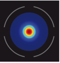
CinCam InGaAs is a plug-and-play solution for laser beam profiling of CW and pulsed lasers in the SWIR spectral range of 900 to 1700 nm.
When it comes to choosing a laser beam profiler, the choice can often be overwhelming. What follows are suggestions to make the right choice for you. All of our laser beam profilers are based on 2D arrays (not scanning slits).
What is my wavelength and am I working with 1 or several wavelengths? This will determine which technology to use (Si based CMOS sensors, InGaAs based Infrared sensors etc) for your laser beam profiling application.
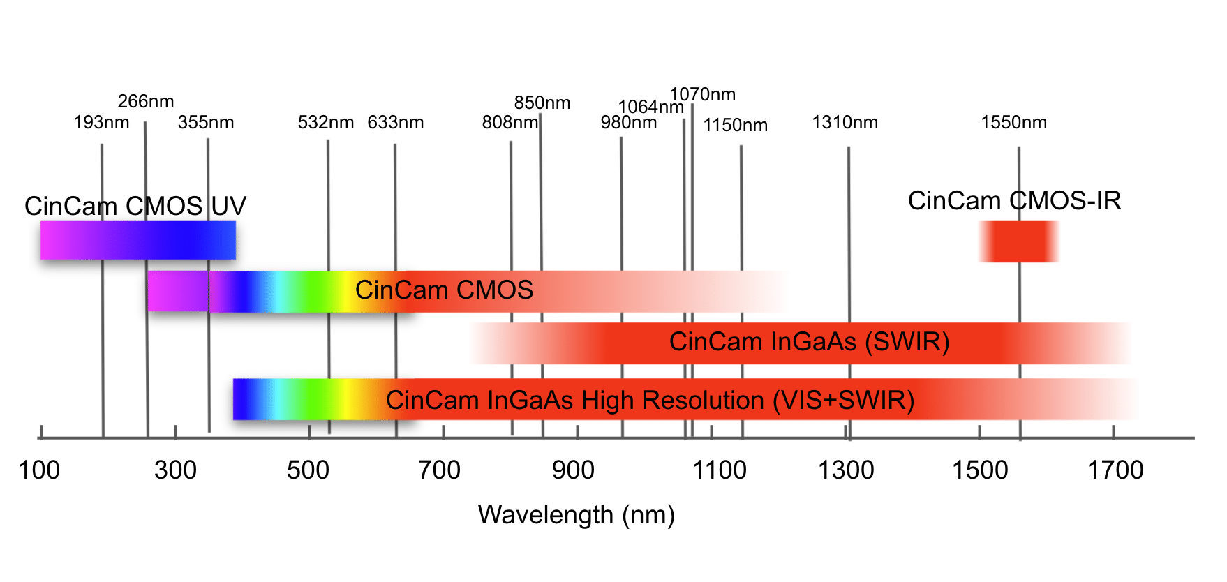
For wavelengths <1150 nm and in some cases <1320 nm, a CMOS or CCD based sensor will do the job. All CMOS and CCD based laser beam profilers we offer have no cover-glass. Nowadays, CMOS sensors are very performant and will be a cost-effective solution in >95% of the cases. CCD sensors have the advantage of being available with larger active areas for applications having multiple beams or large beams (>10mm). The type of neutral density (ND) filter used impacts the cut-on of the sensitivity.
Use an absorptive type filter. Each filter is fabricated from a glass substrate that has been selected for its spectrally flat absorption coefficient in the visible region. By varying the type and thickness of the glass used, an entire line of absorptive ND filter is possible.
By default, all CinCam CMOS laser beam profilers are delivered with a built-in OD3.0 absorptive filter with a wedge to minimize interference effects due to parallel surfaces.
Use a reflective type filter. Reflective ND filters consist of thin film optical coatings, typically metallic, that has been applied to a glass substrate. The coating optimization is available for specific wavelength ranges such as UV, VIS or NIR. The thin film coating primarily reflects light back toward the source. User should take special care to ensure the reflected light does not interfere with the system setup.
This range can be achieved by removing the micro-lens array used typically to increase the fill-factor of each pixel. The glass used blocks UV light and therefore, by removing it, sensitivity as low as 240 nm is achievable.
This range can be achieved using a special fluorescent coating directly on the CMOS sensor. A thin layer of UV to VIS converting coating which absorbs UV light and emits visible light instead is covering the sensor. The robust fluorescent material is ideal for UV imaging. The material shows an excellent quantum yield of nearly 100% for wavelengths below 450 nm and down to 100 nm. In contrast there is a high transparency of the material for wavelengths above 480 nm which gives a very good response even in the visible and near infrared wavelengths.

Can be achieved using a special phosphor coating directly on the CMOS sensor. The coating used is based on a complex and non-charge anti-stokes material with unique emission properties and converts 1495 nm-1595 nm photons to visible and detectable wavelengths without fading or image lag. We offer a non-linearity software correction.
Because of the particles’ size, the effective resolution is 5-9µm no matter how small the pixel pitch of the sensor is.

This requires the use of an InGaAs based sensor. One can achieve high QE from 1µm to 1.6µm with a SWIR sensor or 0.4µm to 1.7µm with a VIS+SWIR sensor.
How to choose the right laser beam profiler model given my beam size for laser beam profiling? Beam size is often taken at 1/e2 for a Gaussian beam. It is important to understand that a 1mm beam size for instance, does not mean that there is 0% energy outside a circle of 1mm of diameter. The tail of the beam, although of small intensity, is necessary in order to compute accurate ISO standard measurements on the beam.
Minimum beam size measurable:
The minimum beam size is defined by the pixel pitch of the camera as well as the number of illuminated pixels.
The accuracy of the size measurement depends on the number of illuminated pixels. 15 pixels will give very high accuracy. Under 12 pixels, the accuracy is acceptable. It is not recommended to profile a laser beam with less than 10 illuminated pixels. Therefore, the minimum measurable beam size of a laser beam profiler is pixel_ pitch (µm) x ~10. For example: the CinCam CMOS 1201 laser beam profiler has a pixel pitch of 5.2µm. Therefore, the minimum beam size recommended is >52µm. The smallest pixel pitch available is 2.2µm (see CinCam CMOS 1204 laser beam profiler and CinCam CMOS PICO laser beam profiler)
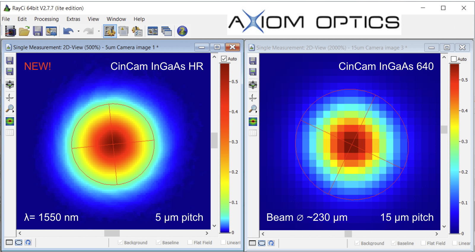
The CinCam InGaAs 1280-HR and 640-HR have a pixel pitch of 5µm and therefore can measure beams down to ~50µm.
Below is a comparison of the same beam @ 1550nm between the CinCam InGaAs 640 and CinCam InGaAs 1280-HR.
Maximum beam size measurable:
The active area of the laser beam profiler sensor will define the maximum beam size measurable. A rule of thumb is to take ~75% of the length in one direction. For example: The CinCam CMOS Nano 1.001 laser beam profiler has an active area of 11.3 x 11.3 mm. Therefore, the maximum beam size measurable is ~8.5mm.
The largest CMOS sensor is the CinCam CMOS Nano 1.001 laser beam profiler with 11.3 x 11.3 mm active area. The largest CCD sensor is the CinCam CCD 3501 laser beam profiler with 36 x 24 mm active area.
What is my beam power and what OD or attenuation do I need? Whether using an absorptive or reflective type ND filter, laser beam profilers allows the maximum peak power of~1W. For power greater than 1W, an attenuation unit can be added directly to the laser beam profiler (works on all CMOS, CCD and InGaAs models thanks to a large spectral range of 190 nm to 2000 nm). The attenuator is based on two uncoated fused silica wedges and is designed for pre-attenuation of high intensity laser beams. The principle is based on the polarization effect by reflection on an optical surface. The s-pol. and p-pol. parts of the laser beam have different reflection factors. Orthogonal arrangement of the wedges compensates the polarization effect and allows neutral attenuation of the laser beam
You can use the prism attenuator up to intensities of 2GW/cm2 for pulse wave and 25kW/cm2 for continuous wave. It is possible to combine with neutral density filters for final power adjustment to the beam profiler sensitivity level. The high performance optical design in compact housing allows precise beam attenuation.
3 models are available: 5W, 100W or 200W.

Do I have limited space in my optical setup? For the CMOS laser beam profilers, there are 3 body styles depending on the available room in the optical setup.
The standard CinCam CMOS laser beam profiler models measure 40 x 40 x 20 mm.

The CinCam CMOS Nano laser beam profiler models measure 29 x 29 x 20 mm with standard body.

The CinCam CMOS PICO laser beam profiler is the smallest beam profiler in the world with only 15 x 15 x 11.5 mm.

Click for more information and technical specs on: CinCam CMOS
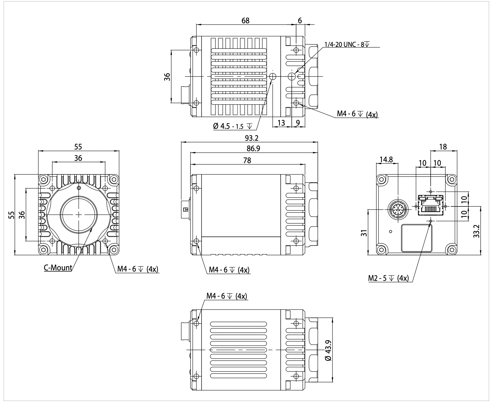
The CinCam InGaAs has the following form factor:
Do I need a special calibration for my application? Go beyond standard laser beam profiling by enabling high performance features for your applications!
RayCi software automatically perform corrections but some corrections require user activation. Please refer to the Rayci Laser Beam Profiling Software user manual for more information. Additional calibrations such as absolute power calibration or angular calibration for divergent sources such as VCSEL are available and must be requested at the time of order.
Saturation level is in some cases linear with input power. Based on this simple principle, the laser beam profiler can be power calibrated to show the absolute laser power in real time. Because the sensor sensitivity depends strongly on the laser wavelength, the calibration has to be done for each target wavelength.
For laser beam profiling applications with a highly divergent beam (typically > ±10°), QE and therefore the sensor response decreases with the angle of incidence. The angular response calibration corrects this effect, thus allowing accurate results.
Know the exact optical position of sensor surface relative to the housing with high accuracy.
The calibration removes pixel sensitivity variations achieved by an illuminated flat field (White homogeneous image). If available, the 2D-View will be permanently corrected with these pixel sensitivity variations.
The background calibration is a process to permanently subtract an acquired background image (reference image) from the live stream. This correction eliminates undesired illumination effects and it includes also a cold and hot pixel correction.
RayCi laser beam profiling software calculates a correction plane from every live frame. This correction plane is a dynamically baseline correction. The software subtracts the correction plane from the live data and corrects the dynamical non-uniformities in the background. Additionally this eliminates the temporal changes in the background level.
Click for more information and technical specs on: CinCam CMOS, CinCam InGaAs and Rayci Software
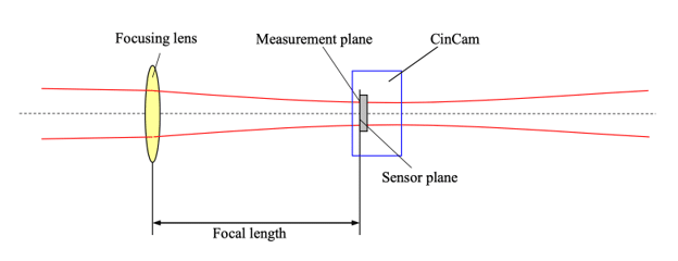
CINOGY’s CinSquare is a compact and fully automated tool to measure the beam quality of CW and pulsed laser systems from the UV to SWIR spectral range. The system consists of a fixed focusing lens in front of a motorized translation stage carrying the camera-based CinCam beam profiler. Its operational robustness and reliability ensures continuous use applications in industry, science, research and development.
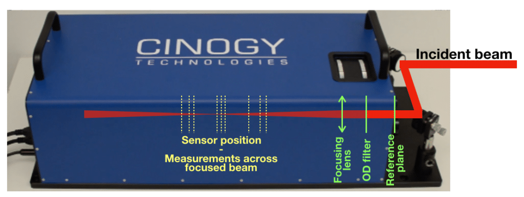
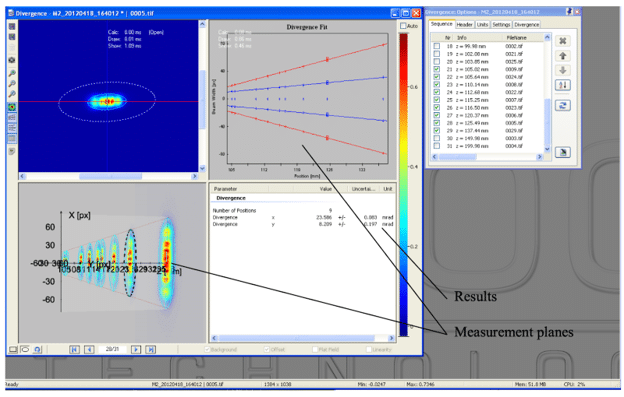
According to ISO 11146-1/2 the CinSquare system measures the complete beam caustic and determines M² waist position, divergence, etc., related to the reference plane. To facilitate its use, the CinSquare system is equipped with two alignment mirrors for exact positioning of the laser beam and a filter wheel for incremental beam attenuation.
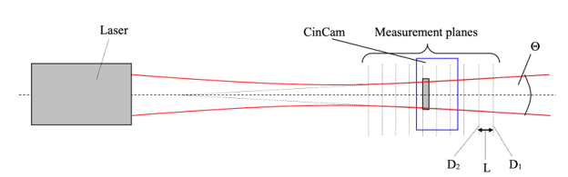
There are several ways to measure the laser beam divergence. We describe here 2 methods for laser beam divergence measurement.
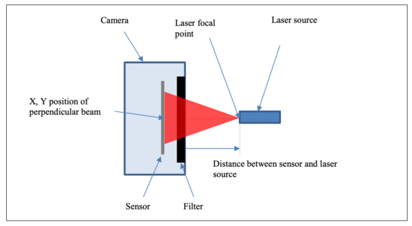
Far-field laser beam divergence measurement using a lens of known focal length. By definition, the full divergence Θ=D/f where D is the diameter of the beam at the focal distance and f the focal length.
By placing the CinCam profiler at the focus distance and inputting the focal length directly in RayCi software, laser beam divergence measurement can be easily achieved.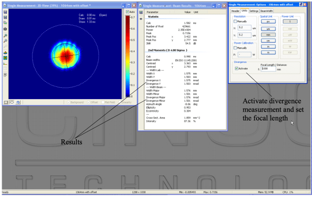
Measurement by direct beam size calculation at several positions in the beam path
By definition, the divergence (full angle) Θ is given by:
Θ=2 arctan(D1-D2)/2L where D1, D2 are the beam diameter at different positions and L the distance between the measurement positions.