Written by Christoph Baranec – University of Hawaii
We at the University of Hawaii are in the process of building and deploying a second generation robotic adaptive optics system called Robo-AO-2[1]. The instrument accepts both starlight and Rayleigh scattered ultraviolet laser light (λ=355nm) from a host telescope, and uses optical relays and lenses to send that light to various wavefront sensor and science cameras. In order to align all of the optics in the instrument, we use high-resolution cameras to measure beam sizes and footprints, shear plates to test for collimation, and Shack-Hartmann wavefront sensors to measure wavefront quality.
For alignment of the first generation Robo-AO system[2], we used a HASO4 BB wavefront sensor from Imagine Optic. The advantages of this wavefront sensor for our application are: it has a useful wavelength range from 350 nm to the visible, where we align our laser wavefront sensor and optical science channels respectively; it can measure converging beams, allowing us to measure the wavefront quality of the final F/41 beam in the system; and was in a compact package that we could easily sneak around our modest sized optical bench.
For the alignment of the Robo-AO-2 system, we also used the HASO4 BB, as it was perfect for aligning the laser wavefront sensor, and for aligning the first optical relay in the system. However, we ran into an issue with the 12 mm diameter collimated beam in the second optical relay being much too large for the HASO4 BB wavefront sensor with its 5.3 mm × 7 mm aperture. The first element of the second optical relay, which collimates light from an intermediate focus after the first relay, is an off-axis parabolic mirror, designated OAP3. Misalignments in OAPs primarily result in additional focus and astigmatism errors, so these are the errors that we first try to mitigate during the alignment process.
Rough alignment of OAP3 is started using shear plates to measure the reflected wavefront curvature in one axis at a time. Once the position of OAP3 has been adjusted such that the shear plates indicate approximately zero curvature in tangential directions to the beam path, we switch to using a Shack-Hartmann sensor for fine-tuning.
We initially used the HASO4 BB to sample the center of the 12 mm diameter beam. The measured the wavefront map and reconstructed Zernike amplitudes appear in Figure 1. The reconstructed Focus mode has an amplitude of -31 nm RMS, with 0° and 45° Astigmatisms having amplitudes of 67 nm RMS and 4 nm RMS respectively. We then rotated the HASO4 BB in its mount by 90° about the optical axis and repeated the measurement (Figure 2). This time we measured the Focus mode with an amplitude of +14 nm RMS, with 0° and 45° Astigmatisms having amplitudes of 3 nm RMS and 19 nm RMS respectively. Theoretically, the measured focus value should be independent of rotation of the wavefront sensor, and the measured astigmatism values should have switched signs with the 90° rotation. From this, we concluded that we were unable to make an accurate measurement of the wavefront with this wavefront sensor, and therefore were unable to properly align this optic.
[1] http://robo-ao.org; https://arxiv.org/abs/1806.01957
[2] https://arxiv.org/abs/1407.8179
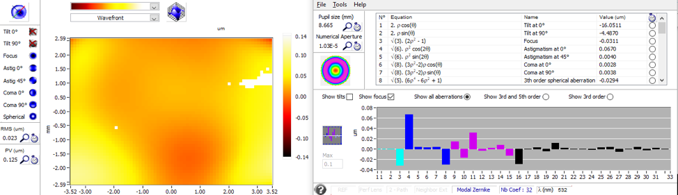
Figure 1. Measured phase and reconstructed wavefront of the central 5.3 mm × 7 mm of 12 mm diameter beam after reflection from OAP3.
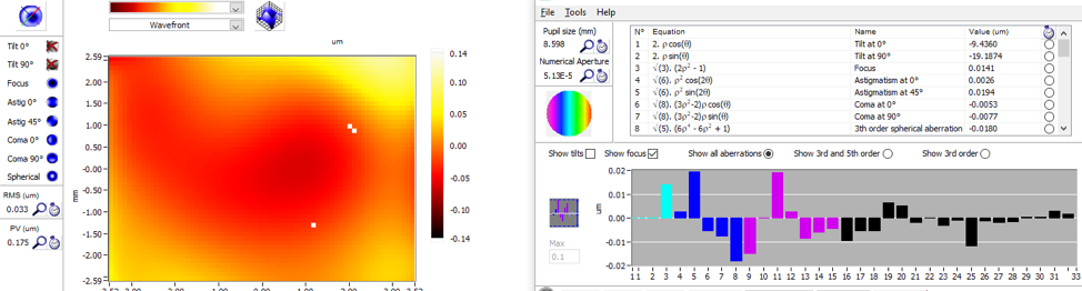
Figure 2. Same as figure 1, but with the wavefront sensor rotated by 90° about the optical axis.
We then switched to using a HASO3-128GE2 wavefront sensor with an appropriately sized 14.6 mm × 14.6 mm aperture. This can be seen in figure 3, with the wavefront sensor pointed toward OAP3. With a wavefront sensor that can sample the entire beam, we were able to get a much more accurate measurement of the wavefront: Focus, +30 nm RMS, and 0° and 45° Astigmatisms -13 nm RMS and -33 nm RMS respectively. From here we were able to refine the alignment of OAP3 to essentially null out these three low order modes (see figure 4). By using the properly sized wavefront sensor for the beam in test, we were able to reduce the RMS wavefront error from 55 nm to 38 nm and the Peak-to-Valley wavefront error from 244 nm to 197nm.
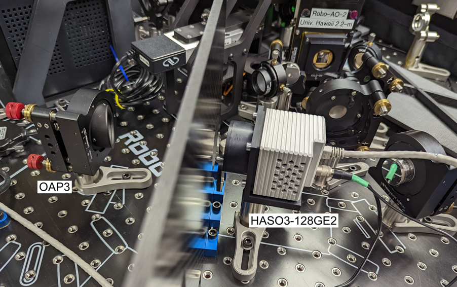
Figure 3. Using the HASO3-128GE2 wavefront sensor to measure the collimated beam reflecting off of OAP3 during the assembly and alignment of the Robo-AO-2 adaptive optics system.
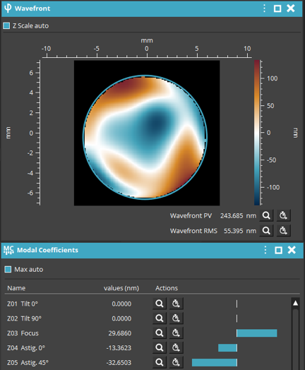
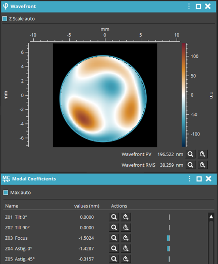
Figure 4. The measured wavefront error from the HASO3-128GE2 before (left) and after (right) alignment of OAP3.
To learn more about wavefront sensing applications, click HERE.
To learn more about adaptive optics applications, click HERE.
To view more Imagine Optic wavefront sensors, click HERE.