A Shack Hartmann wavefront sensor (SHWFS) is one of the most powerful tools for diagnosing and fixing optical alignment because it measures what the beam’s wavefront actually looks like (tilt, focus, astigmatism, coma, higher-order aberrations).
In a SHWFS, a microlens array samples an incoming wavefront into spots focused on a detector (camera). Each spot lateral position allows calculation – knowing the focal of the microlens – of wavefront slopes. By integrating these slopes, the software reconstructs the wavefront map and gives Zernike coefficients (tilt, defocus, astigmatism, coma, etc.).
Want to learn more about wavefront sensors? Visit our Application Page.
5 reasons why you should use a Shack Hartmann wavefront sensor for optical alignment
- Live measurement: SHWFS run in real time. You can align a mirror, lens or complex systems and immediately see how the wavefront RMS responds, as well as the aberrations. This is also one reason why SHWFS are used in adaptive optics systems.
- Aberrations decomposition: The projection into Zernike modes indicates what type of misalignment you have. For example: tilts result from beam pointing error, defocus from wrong lens spacing/focus, astigmatism from optics tilts or stress, and coma from decentering of lens/mirror..
- Insensitive to vibrations: The reconstruction still works in the presence of vibration; a controlled environment (vibration, temperature, air flow) is not mandatory.
- Absolute measurement: Thanks to a factory calibration, SHWFS acquires an absolute measurement:
- 𝛌 /100 RMS accuracy
- 𝛌 /200 RMS sensitivity
Imagine Optic delivers a certificate for every wavefront sensor stating its dynamic range and wavelength range in absolute measurement mode. To learn more about absolute measurement, click HERE.
- Portable and Flexible: It works with broadband or monochromatic light, collimated or converging beams. Because it is small, it can be easily added to optical benches, laser beamline or fiber-coupling systems for example.
Why is Off-axis parabola alignment a challenge?
An off-axis parabola (OAP) is a “cut-out” portion of the parent paraboloid, tilted relative to the axis. It is designed to preserve the parent paraboloid’s imaging/focusing properties, but only if positioned exactly right.
This means OAPs do not have a clear axis of symmetry to help alignment: you can’t simply point and center the beam. Moreover, translational and rotational errors are strongly coupled in an OAP, which reduces the number of degrees of freedom for the alignment. Even small tip, tilt, or decenter errors cause aberrations like coma and astigmatism, which quickly degrade performance.
This is why the optical alignment of an OAP requires precise metrology instruments and procedures. In this blog we present both instruments and steps one can use and follow in order to take on this challenge!
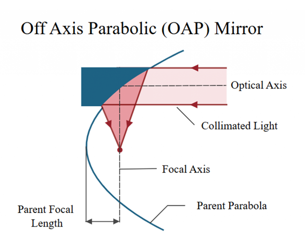
Figure 1: Off-Axis parabolic mirror: Collimated light focuses into an off-axis focal point – source: meetoptics
Using a Shack Hartmann wavefront sensor to align an off-axis parabola
In order to expand the capabilities of Shack-Hartmann wavefront sensors, for example, to characterize large mirrors, Imagine Optic developed the R-FLEX platform.
It is a self-illuminated measurement platform that allows users to quickly and optimally build any optical configuration to align/characterize larger/faster optics.
The R-FLEX is comprised of a wavefront sensor, a metrology source and plug-in focusing modules with different f/# allowing optics characterization in transmission, in double path or in reflection as shown in the figure below.
In order to be used with a large range of optical systems, Imagine Optic provides focusing modules with different f/#, to be inserted into the R-FLEX.
It is compatible with most of the HASO and LIFT wavefront sensors from Imagine Optic: https://www.imagine-optic.com/haso-table/
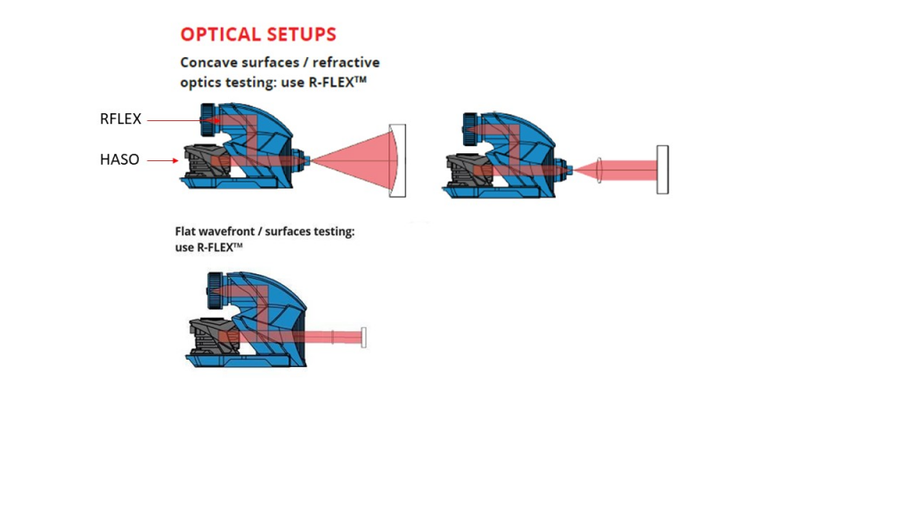
Figure 2: Example of optical setups with R-FLEX – in reflection or transmission for both collimated (with focusing modules) and diverging beams (without)
Setup
The optical characterization of an off-axis parabola using a Shack Hartmann wavefront sensor on its R-FLEX platform is divided into two steps:
- Rough alignment, by eye
- Fine alignment, with WAVEVIEW User Interface software
The only equipment needed is:
- The R-FLEX platform equipped with:
- A wavefront sensor, here the HASO 126 Broadband
- A metrology source-wavelength is not relevant for this use case involving reflective components
- A focusing module with a numerical aperture matching the parabola aperture
- A reference mirror, here a lambda/20 PV (from Edmund Optics)
The setup consists of positioning the R-FLEX output focused spot at the center of curvature of the off-axis parabola (1). This specific position creates a collimated beam (2) that reflects onto a reference mirror (3) and returns to the parabola, the focusing module, and the wavefront sensor (4).
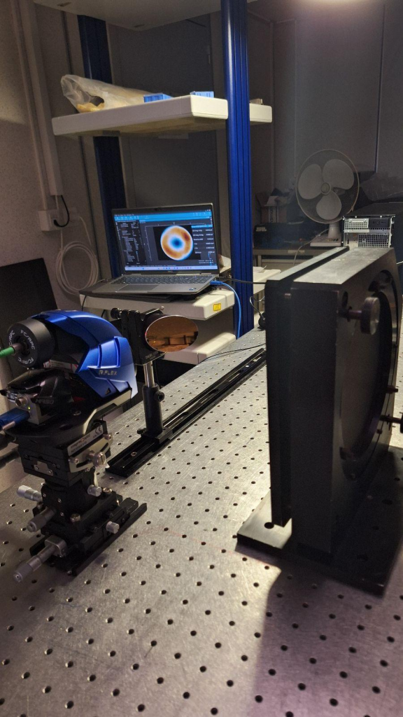
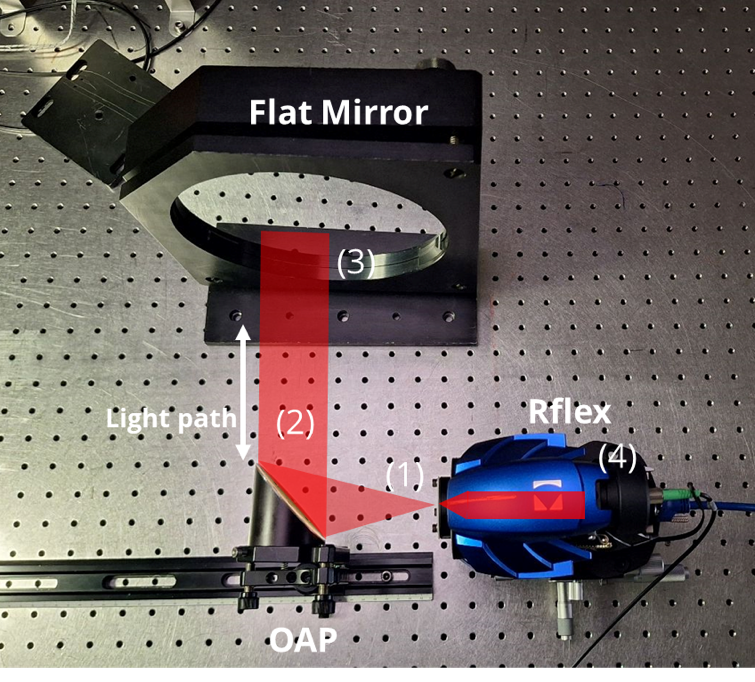
Figure 3: Optical set up (top) and light path (bottom)
Rough alignment:
Step 1: Place the R-FLEX and the parabola so that the focused output beam and the parabola focal plane are at the same positions and heights.
Step2: Adjust this position in order to get:
– The same output beam size at different positions along the optical axis, here a 2-inch roughly collimated beam
– The beam reflection focusing back onto the alignment screen of the module’s hole – use the tip tilt of the flat reference mirror to do this.
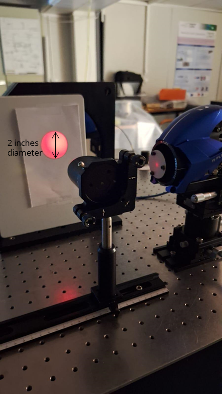
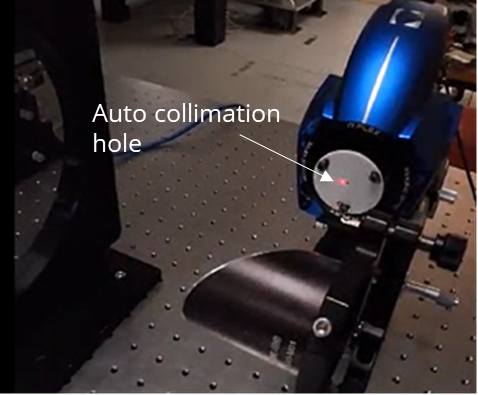
Figure 4: Beam diameter and coarse alignment
Note: For each parabola position, there is a corresponding position of the flat mirror that will produce a perfectly collimated beam. Although several configurations are possible only one minimizes the wavefront error. The objective is to maintain the overall optical system as straight as possible, especially when aligning multiple parabolas.
Once the rough alignment can no longer be improved by eye, the fine alignment can start. This is when the user can open the WaveView software.
Fine alignment:
Below is a typical starting point after opening the software. The beam is centered on the sensor thanks to the rough alignment, but the tilts, the astigmatism values and therefore the wavefront error are not minimal.
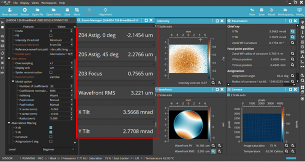
Figure 5: Parameters checking in WaveView software before fine alignment
User specifications: We consider the fine alignment done when the astigmatism values in both directions are <1µm and x and y tilts <0.5°.
Step 1: Minimize curvature by translating the parabola along the optical axis
Step 2: Minimize 45° astigmatism using x and y tilts on the parabola’s mount. Make sure that you are still collimated. This may require a few iterations.
Step 3: Do the same for the astigmatism at 0°
Step 4: Minimize the focus and x/y tilts values
This is the typical result one can achieve:
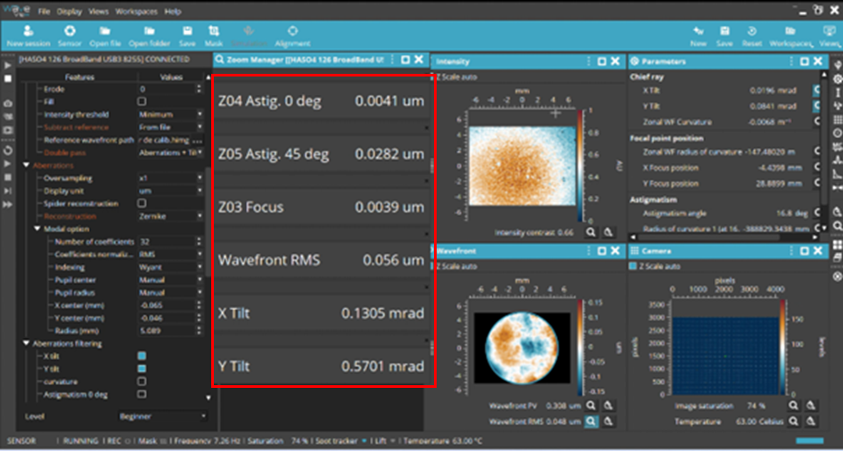
Figure 6: WaveView software after fine alignment
Analysis of the results
The wavefront error went down 56 nm, the focus value close to 4 nm, indicating that we are very well collimated (radius of curvature of 100+ meters). Astigmatisms at 0° and 45° went from 2 µm to <30 nm RMS. Tilts have been minimized, ensuring autocollimation and confirming that we are measuring the optical aberrations of the parabola itself.
Specification of the parabola:
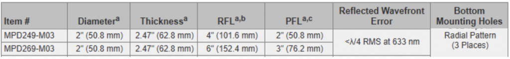
Note: The manufacturer claims λ/4 RMS wavefront error, 160 nm at 635 nm. However, our result of 56 nm RMS (Figure 6), is better than expected. The reason is that we used a focusing module lower than the off-axis parabola. Therefore, we are not illuminating the entire aperture of the off-axis parabola, which means not characterizing the entire diameter and are seeing less aberrations.
This shows the importance of using the right module to ensure the wavefront error value is not over or underestimated. Still all the steps presented remain fully relevant.
Conclusion:
Shack Hartmann wavefront sensors can be easily used to align and characterize many different optics and optical systems.
When paired with the RFLEX platform and associated with the high-performing wavefront analysis software WAVEVIEW, respectively manufactured and developed by Imagine Optic, optical testing setups are drastically simplified.
One of the applications of such a system presented here is the alignment of an off axis parabola. By following specific steps in the right order, the alignment of complex optics becomes quick and easy. This is why this system is also called the “Optical Engineer Companion.”
You may ask…
- Can I do this at different wavelengths? Absolutely!
Learn more here: https://www.axiomoptics.com/blog/optical-metrology-with-a-supercontinuum-laser/
- Can I use a hexapod to assist me? Absolutely!
Learn more here: https://www.imagine-optic.com/optical-alignment-of-a-telescope-with-a-shack-hartmann-wavefront-sensor/
- Can I measure the flatness? Absolutely!
Learn more here: https://www.imagine-optic.com/flatness-measurement-when-surface-flatness-gets-critical/
For more information, contact us [email protected]