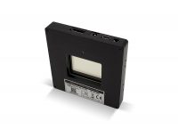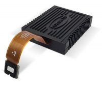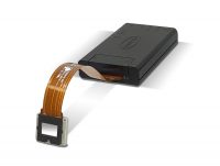


Amplitude Spatial Light Modulator
Display Type
Reflective LCOS
Resolution
1920 x 1080
Pixel Pitch
8.0 µm
Fill Factor
93%
Active Area
15.36 x 8.64 mm (0.7" diagonal)
Signal Formats
HDMI - HDTV Resolution
 Description
 Specifications
 Publications
 More Information
HOLOEYE Amplitude Spatial Light Modulator for Programmable Intensity Control
The HOLOEYE HEO 7020-1 6001 is a lab-ready amplitude spatial light modulator that sets the brightness of light pixel by pixel. Built on a 1920 x 1080 reflective LCOS microdisplay with an 8.0 µm pixel pitch and 93% fill factor, it turns any 8-bit image into a 256-level intensity mask across a 15.36 x 8.64 mm active area.
HOLOEYE offers two versions, one optimized for the visible range (420-650 nm) and one for the near infrared up to 1100 nm, each with a specified contrast greater than 1000:1. The SLM is addressed over HDMI at 60 Hz, synchronizes with cameras through a trigger output, and can run standalone from its ARM-based driver. Axiom Optics helps researchers specify the full optical train around it, from polarizing optics to projection lenses, so the system delivers the contrast and resolution the panel is capable of.
Direct intensity control
Pixel value maps to brightness. No hologram or phase retrieval step between your pattern and the light.
Full HD at 8.0 µm
Two million pixels and 256 gray levels for fine masks, gradients and apodization profiles.
Lab-ready kit
Display, driver, mounts, cables, software and documentation in one package, built like HOLOEYE phase SLMs for easy integration.
How an Amplitude SLM Controls Light
HOLOEYE uses a vertically aligned nematic (VAN) liquid crystal operated in normally black mode. With no drive signal the molecules stand perpendicular to the panel, light reflects without any change in polarization, and crossed polarization optics block it. Raising the gray level tilts the molecules, the cell becomes birefringent, and a growing share of light is rotated into the polarization that reaches your sample. The result is an intensity modulator whose dark state is set by the liquid crystal and your polarizers rather than by a voltage you have to hold.
Amplitude modulation explorer
Step through gray levels to see how a normally black LCOS pixel turns polarization into intensity.
The liquid crystal stands vertical and adds no retardance. Reflected light keeps its input polarization, so the polarizing beam splitter sends it back toward the source and the pixel stays dark. That is what normally black means.
End points match with or without correction; the error lives in the mid-tones.
The liquid crystal stands vertical and adds no retardance. Reflected light keeps its input polarization, so the polarizing beam splitter sends it back toward the source and the pixel stays dark. That is what normally black means.
End points match with or without correction; the error lives in the mid-tones.
As the molecules tilt, birefringence converts part of the light to the orthogonal polarization. The beam splitter passes only that component to the output, so intensity follows the gray level.
With a linearizing lookup table, gray 64 lands on 25% intensity, so 256 levels map evenly across the range.
As the molecules tilt, birefringence converts part of the light to the orthogonal polarization. The beam splitter passes only that component to the output, so intensity follows the gray level.
Without correction, gray 64 gives 15% instead of the 25% a linear response would deliver.
As the molecules tilt, birefringence converts part of the light to the orthogonal polarization. The beam splitter passes only that component to the output, so intensity follows the gray level.
With a linearizing lookup table, gray 128 lands on 50% intensity, so 256 levels map evenly across the range.
As the molecules tilt, birefringence converts part of the light to the orthogonal polarization. The beam splitter passes only that component to the output, so intensity follows the gray level.
Without correction, gray 128 gives 50% instead of the 50% a linear response would deliver.
As the molecules tilt, birefringence converts part of the light to the orthogonal polarization. The beam splitter passes only that component to the output, so intensity follows the gray level.
With a linearizing lookup table, gray 192 lands on 75% intensity, so 256 levels map evenly across the range.
As the molecules tilt, birefringence converts part of the light to the orthogonal polarization. The beam splitter passes only that component to the output, so intensity follows the gray level.
Without correction, gray 192 gives 86% instead of the 75% a linear response would deliver.
The double-pass retardance reaches a half wave (π). Polarization is fully rotated and the beam splitter routes all of the modulated light to the output.
End points match with or without correction; the error lives in the mid-tones.
The double-pass retardance reaches a half wave (π). Polarization is fully rotated and the beam splitter routes all of the modulated light to the output.
End points match with or without correction; the error lives in the mid-tones.
Idealized model for illustration: crossed polarization through a polarizing beam splitter, uncorrected curve assumes retardance rising linearly with gray level, molecule tilt drawn schematically. Measured response depends on wavelength and calibration.
Because the relationship between gray level and intensity is not naturally linear, HOLOEYE provides a USB connection for advanced calibrations. Axiom Optics can help you set up a response that is linear in intensity at your working wavelength.
Two Versions: Visible and Near Infrared
Both versions share the same 1920 x 1080 panel, driver and kit. Choose the one that matches your laser.
Wavelength in nm. Dashed lines mark the 633 nm and 1064 nm reference wavelengths for reflectivity and contrast.
HES 7020-1 6001-VIS-154
- Wavelength range
- 420-650 nm
- Reflectivity
- 72% @ 633 nm
- Contrast
- >1000:1 @ 633 nm
HES 7020-1 6001-NIR-164
- Wavelength range
- 650-1100 nm
- Reflectivity
- 76% @ 1064 nm
- Contrast
- >1000:1 @ 1064 nm
Getting Full Contrast From the System
HOLOEYE specifies contrast greater than 1000:1, and points out that contrast depends strongly on the optical system and the quality of the polarizer components. In practice the polarizing beam splitter or analyzer you pair with the SLM often decides the dark level you actually see. The kit ships with a test polarizer for a first check; for measurement-grade work, plan your polarizing optics as carefully as the SLM itself.
Contrast budget
Choose the extinction ratio of your polarizer or polarizing beam splitter to estimate end-to-end contrast.
91:1 system contrast. A dark pixel still passes about 1.10% of full brightness.
The polarizing optics are the weak link. Upgrading them is the fastest way to recover dynamic range.
333:1 system contrast. A dark pixel still passes about 0.30% of full brightness.
The polarizing optics are the weak link. Upgrading them is the fastest way to recover dynamic range.
500:1 system contrast. A dark pixel still passes about 0.20% of full brightness.
Matched optics halve the panel’s contrast, because dark-state leakage from both elements adds.
909:1 system contrast. A dark pixel still passes about 0.11% of full brightness.
With high-extinction optics, system contrast approaches the panel’s own specification.
990:1 system contrast. A dark pixel still passes about 0.10% of full brightness.
With high-extinction optics, system contrast approaches the panel’s own specification.
First-order estimate: dark-state leakage from the panel (taken at the 1000:1 specification floor) and from the polarizing optics adds. Scatter, angle of incidence and wavelength mismatch reduce real-world contrast further. Bars use a log scale.
Projecting Patterns: Pixel Size at the Sample
For maskless photo-patterning, structured illumination and optogenetic-style stimulation, the SLM is usually imaged onto the sample through demagnifying optics. The projected pixel is the 8.0 µm pitch divided by the demagnification, and the field shrinks by the same factor.
Projected pixel and field size
Pick the demagnification of your projection optics to see pixel size and field at the sample plane.
50 µm window at the sample, one cell per projected pixel
50 µm window at the sample, one cell per projected pixel
50 µm window at the sample, one cell per projected pixel
50 µm window at the sample, one cell per projected pixel
50 µm window at the sample, one cell per projected pixel
At 0.40 µm the projected pixel is comparable to or below the Abbe limit λ/(2NA) of typical visible objectives (about 0.33 µm at 633 nm with NA 0.95). The objective, not the SLM, sets the finest printable feature.
50 µm window at the sample, one cell per projected pixel
At 0.16 µm the projected pixel is comparable to or below the Abbe limit λ/(2NA) of typical visible objectives (about 0.33 µm at 633 nm with NA 0.95). The objective, not the SLM, sets the finest printable feature.
Geometric scaling of the 8.0 µm pitch and the 15.36 x 8.64 mm active area. Aberrations and the 93% fill factor are not modeled.
Amplitude SLM Applications
Researchers use the HOLOEYE amplitude SLM wherever a reconfigurable intensity mask beats a fixed one, from beam shaping to computational imaging. More studies are listed under the Publications tab.
Applications
Select an application to see the kind of amplitude mask it uses.
Beam shaping and apodization
Load a transmission map that attenuates the bright core of a Gaussian beam to produce a flat-top or custom profile, or apodize an aperture to suppress edge ringing. Because amplitude control is direct, the mask is simply the target profile divided by the input profile, with no hologram computation.
Light-driven patterning of materials
Project programmable illumination patterns as reconfigurable masks for photo-patterning, photorefractive writing and optically induced electrodes, without fabricating a new physical mask for each design.
Research using this SLM
Single-pixel and computational imaging
Display a sequence of structured illumination or detection masks and reconstruct an image from a single-element or low-light detector. The approach suits imaging through scattering media and wavelengths where pixelated cameras are costly.
Research using this SLM
Optical computing and neural networks
Use 256 gray levels per pixel as programmable optical weights for matrix operations, optronic neural networks and analog physical simulators with an optical feedback loop.
Research using this SLM
Pump shaping for lasers and photonics
Shape the spatial profile of an optical pump on a gain medium to select, steer or tune emission, a common technique in random laser and active photonics research.
Research using this SLM
Driver, Connectivity and Standalone Operation
The HEO 7020-1 6001 driver uses an HDMI interface for addressing images, a USB connection for advanced calibrations, and a trigger sync output for external devices. Its dual-core ARM Cortex-A9 processor also lets the SLM run patterns on its own.
Three ways to drive the SLM
Pick an operating mode to highlight the signal path.
The host PC addresses the SLM as an HDMI display at 60 Hz, so any software that can draw a full-screen image can drive it. A USB link handles advanced calibrations, and the trigger sync output tells your camera or DAQ when a new frame is on the panel.
HOLOEYE’s driver runs an embedded Linux SMP system on a dual-core ARM Cortex-A9 with a library that gives full control and supervision of the display and driver. Connect over Serial or Ethernet-over-USB2 (RNDIS) and build custom functions with a standard Ubuntu GCC cross-compile toolchain.
Amplitude SLM or Phase SLM?
An amplitude SLM blocks the light it does not pass, trading efficiency for a direct pixel-to-intensity map. A phase-only SLM redirects light by diffraction and keeps most of it, which is why it leads for holography, beam steering and adaptive optics. Answer two questions to find the right HOLOEYE modulator in the Axiom Optics lineup.
Which HOLOEYE SLM fits your setup?
You are on the right page: Amplitude SLM, VIS-154
Covers 420-650 nm with 72% reflectivity and greater than 1000:1 contrast at 633 nm, per HOLOEYE. Request a quote with the VIS version.
You are on the right page: Amplitude SLM, NIR-164
Covers 650-1100 nm with 76% reflectivity and greater than 1000:1 contrast at 1064 nm, per HOLOEYE. Request a quote with the NIR version.
Talk to Axiom Optics
The amplitude SLM stops at 1100 nm. Axiom Optics can assess whether a phase-only LCOS such as the PLUTO-2.1 (TELCO and SWIR versions reach 2500 nm), set up between polarizers, meets your intensity requirements. Contact Axiom Optics.
Start with the PLUTO-2.1
HOLOEYE’s most versatile 1080p phase SLM. For 4K resolution and 3.74 µm pixels see the GAEA-2.1; for speed, the LETO-3; for the smallest package, the LUNA; for analog phase stability, the ERIS-1.1.
PLUTO-2.1 NIR or ERIS-1.1 NIR
The PLUTO-2.1 NIR versions and the ERIS-1.1 NIR-153 (420-1100 nm) cover the near infrared, and the GAEA-2.1 NIR version adds 4K resolution.
PLUTO-2.1 TELCO or SWIR
The PLUTO-2.1 offers TELCO (1400-1700 nm) and SWIR (1700-2500 nm) versions; the GAEA-2.1 and ERIS-1.1 also have TELCO versions.
LC 2012 transmissive SLM
The LC 2012 is HOLOEYE’s budget transmissive SLM for 400-850 nm, well suited to teaching and proof-of-concept work with both amplitude and phase setups.
LC 2012, or step up to this SLM
The LC 2012 reaches 850 nm. Beyond that, the NIR version of this amplitude SLM covers up to 1100 nm.
Talk to Axiom Optics
There is no budget transmissive option past 850 nm. Contact Axiom Optics to discuss the most economical route for your band.
Choose a goal and a wavelength band to get a recommendation.
Now choose what you need to control.
Now choose a wavelength band.
Correcting aberrations rather than shaping light? Compare options in our guide, Deformable Mirror vs. Spatial Light Modulator, or browse all spatial light modulators.
Amplitude SLM FAQ
What is an amplitude spatial light modulator?
An amplitude spatial light modulator (SLM) is a pixelated device that sets the intensity of light at each point across a beam. The HOLOEYE amplitude SLM uses a 1920 x 1080 reflective LCOS microdisplay with 8.0 µm pixels, so each of its roughly two million pixels can be set to one of 256 gray levels to pass, attenuate or block light.
How does the HOLOEYE amplitude SLM modulate intensity?
The display uses a vertically aligned nematic (VAN) liquid crystal in normally black mode. With no drive the pixel adds no retardance and appears dark between crossed polarization optics. Increasing the gray level tilts the liquid crystal, rotating part of the light's polarization so it passes the analyzer or polarizing beam splitter. Intensity therefore follows the 8-bit gray value.
Should I choose the VIS or the NIR version?
Choose by your laser wavelength. The HES 7020-1 6001-VIS-154 covers 420-650 nm with 72% reflectivity at 633 nm. The HES 7020-1 6001-NIR-164 covers 650-1100 nm with 76% reflectivity at 1064 nm. HOLOEYE specifies greater than 1000:1 contrast for both at their reference wavelengths.
What contrast ratio can I expect in my system?
HOLOEYE specifies greater than 1000:1 at the reference wavelength and notes that contrast depends strongly on the optical system and on the quality of the polarizer components. As a first-order rule, leakage from the panel and from the polarizing optics adds, so optics with an extinction ratio well above 1000:1 are needed to approach the panel specification.
When should I use an amplitude SLM instead of a phase-only SLM?
Use an amplitude SLM when you need a direct, one-to-one map between pixel value and intensity, such as pattern projection, programmable masks, apodization or single-pixel imaging, with no hologram computation. Use a phase-only SLM such as the PLUTO-2.1 when light efficiency matters most, for holography, beam steering, multi-spot generation or wavefront correction, because it redirects light rather than blocking it.
How does an LCOS amplitude SLM compare with a DMD?
A digital micromirror device switches each mirror between two states at very high binary pattern rates and builds gray levels by time multiplexing. The HOLOEYE amplitude SLM sets 256 gray levels per pixel within each 60 Hz frame and requires polarized light. A DMD suits very fast binary patterns; the LCOS amplitude SLM suits true gray-level masks in a single frame at 8.0 µm pitch.
Can the amplitude SLM run without a computer?
Yes. The driver has a dual-core ARM Cortex-A9 processor running embedded Linux and can play a slideshow of images loaded from a USB flash drive through its OTG slot or from internal memory. Custom functions can be programmed on the driver with a standard Ubuntu GCC cross-compile toolchain.
How do I synchronize the SLM with a camera?
Use the trigger sync output on the driver unit. It lets a camera, detector or DAQ acquire in step with the frames displayed on the SLM. Images are addressed over HDMI at a 60 Hz input frame rate.
What is included with the amplitude SLM kit?
The kit includes the amplitude display with flex cable, driver unit, display mount, device mount, power supply and cable, USB to mini USB cable, HDMI cable, safety instructions and a quick-start guide with a test polarizer, and a USB flash drive with the software package and documentation.
Specify your amplitude SLM setup
Tell Axiom Optics your wavelength, contrast target and projection optics. We will confirm the right version and help you plan the polarizing optics around it.
Amplitude SLM Scope of Supply
- Amplitude display including flex cable

- Driver unit
- Display mount
- Device mount
- Power supply + cable
- USB/mini USB cable
- HDMI cable
- Safety instructions & quick start guide (test polarizer inside)
- USB flash drive with software package and documentation