
Hexapods
Pivot points and coordinate frames: the hexapod concept that trips up new users
A hexapod does exactly what it is told. The trouble is that a rotation command is meaningless on its own: it only means something once you say what it is rotating about and in which frame the numbers are expressed. Nearly every early frustration with a six degree of freedom platform traces back to those two settings, and both are fixed in software in a matter of minutes.
01. The moment it goes wrong
The first move that does not do what you expected
A new hexapod arrives, the payload goes on, and someone types a five degree rotation to check that everything works. The platform tilts correctly. The optic mounted on top swings several centimetres sideways and leaves the field of view entirely.
Nothing has failed. The controller solved for six leg lengths that produce exactly five degrees of rotation, and it did so about the point it had been given, which was almost certainly the center of the platform. Everything mounted above that point travelled through an arc, and the further up it sat, the longer that arc was.
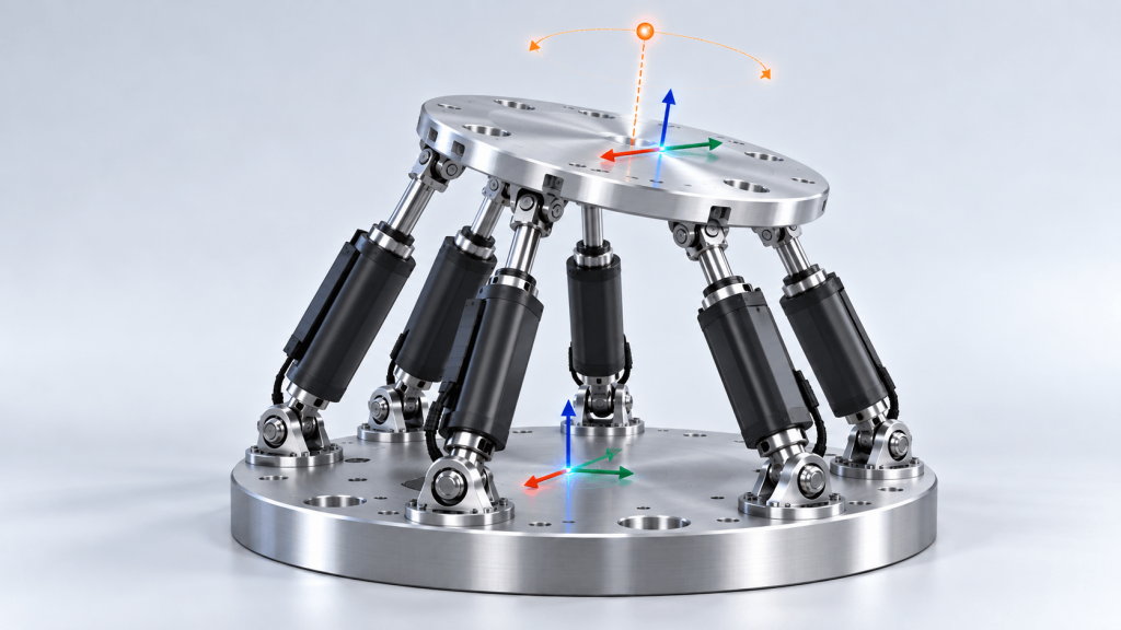
This is the concept that separates a hexapod from the stacked stages most people arrive from. On a stack of rotation stages the center of rotation is built into the hardware and you work around it. On a hexapod there is no physical bearing at the center of rotation at all. The pivot is a coordinate, it can be anywhere, and until you decide where, the controller will keep using whatever it was last given.
A rotation command is incomplete without a pivot and a frame. Supply both and a hexapod becomes the most intuitive positioner in the lab. Leave them at their defaults and it behaves like a machine with a mind of its own.
02. The pivot point
The same command, four different results
Below is a hexapod carrying an optic 150 mm above the platform. Every tab sends the identical instruction: rotate ten degrees about Y. The only thing that changes between them is the pivot coordinate.
One command, four outcomes
Move the pivot, watch the payloadPivot at the platform center
The factory default on most controllers, and the reason the first move surprises people. Rotating about the platform center swings everything mounted above it through an arc. The further your point of interest sits from the platform, the larger that arc gets.
Pivot at the tool tip
Put the pivot on the feature you actually care about and the rotation happens in place. The tool tip stays exactly where it was and only its orientation changes. This is what almost every alignment task wants, and it is a single coordinate entry away.
Pivot at the remote point above the tool
A pivot can sit anywhere in space, including somewhere no hardware exists. Put it at a focal point, a beam waist or a virtual sample center and the tool swings the opposite way from the default case. Same command, opposite direction.
Pivot at the base center
The other common default, and the one that produces the largest excursion. Everything above the base pivots as one long lever, so a modest commanded angle throws the payload a long way sideways and eats a large share of the linear travel.
Every case sends the identical instruction: rotate ten degrees about Y. Nothing about the hexapod, the payload or the command changes between them. Only the pivot coordinate does, and the tool tip ends up 26 mm one way, 26 mm the other way, 61 mm away, or exactly where it started.
The spread across those four cases is 87 mm at the same commanded angle, and in two of them the tool moves in opposite directions. Nobody debugs their way to the right answer by nudging axes. The fix is to decide where the rotation should happen and tell the controller, which on a Symetrie system is a coordinate entered in SYM_Positioning or set through its API.
03. Coordinate frames
Four frames and what each one is for
The second half of the problem is the frame. A coordinate on its own says nothing until you know what it is measured from, and a hexapod has several candidates that all agree with each other at the zero pose and then quietly diverge.
Four frames, and what each one is for
Pick a frameMachine frame Fixed to the machine
The one invariant frame. Its origin sits at the center of the base plate and its axes are fixed to the world, so it never moves, whatever the platform does. The user frame is defined relative to it, and every other frame ultimately traces back to it. Lose track of where it points and nothing downstream can be trusted.
Lifecycle: Invariant. Set by the manufacturer, and the reference for the user frame.
Platform frame Rides the moving platform
Attached to the center of the mobile platform, and not invariant: it moves with every commanded pose. At the zero pose it coincides with the machine frame, which is exactly why the two are so easy to confuse. The moment you command a pose they separate, and a coordinate that meant one thing before the move means something different after it. The object frame is defined relative to this one, so it inherits every move.
Lifecycle: Moves with the platform. Coincides with the machine frame only at zero pose.
User frame Your setup, not the machine’s
A frame you define relative to the machine frame to match how your experiment is actually laid out. Because the machine frame is invariant, the user frame stays fixed in the room too. Align it with the beamline, the optical axis or the edge of the fixture, and commanded moves start reading in the language of the setup rather than the language of the machine.
Lifecycle: Defined relative to the machine frame. Set once during setup, then left alone.
Object frame Attached to the payload
A frame you define relative to the platform frame, fixed to whatever is mounted on it: the mirror vertex, the sample center, the probe tip. Because the platform frame is not invariant, the object frame travels with the payload through every move. This is normally where you want the pivot, and defining it properly is the single change that makes a hexapod feel intuitive instead of unpredictable.
Lifecycle: Defined relative to the platform frame. Redefine whenever the payload or fixture changes.
Frame names follow Symetrie’s convention in SYM_Positioning. The dashed links show how the frames are defined: the user frame relative to the machine frame, which is invariant, and the object frame relative to the platform frame, which moves with every pose.
The four frames work as two pairs. The user frame is defined relative to the machine frame, which is invariant, so the user frame stays fixed in the room whatever the platform does. The object frame is defined relative to the platform frame, which is not invariant, so the object frame travels with the payload through every move. Knowing which frame a coordinate is anchored to tells you whether it will still point at the same place after the next move.
That last point is the trap. At the zero pose the machine and platform frames sit on top of each other, so a coordinate that works during setup appears to confirm that everything is correct. The disagreement only shows up once the platform has moved, which is exactly when it is hardest to interpret.
04. The hidden cost
Why a remote pivot eats your travel
A hexapod can put its pivot anywhere, but distance is not free. Rotating about a point far from the platform forces the platform itself to translate, and that translation comes out of the same linear budget everything else is drawing on.
What a distant pivot costs you
InteractiveThe datasheet condition. Angular travel figures are quoted with the center of rotation at the origin, and at that point the platform barely translates at all to produce a rotation. Every number in the specification table assumes this.
A short standoff, typical of a small optic mounted close to the platform. The translation cost is real but modest, and on most units it disappears into the available linear travel without anyone noticing.
A tall fixture or a sample held above the platform. Now the platform is translating a couple of centimetres to deliver a few degrees, and that translation is coming straight out of your linear budget.
A remote pivot well away from the hardware, such as a distant focal point. The platform has to sweep further than many hexapods can travel, which is why the achievable angle collapses long before the datasheet figure is reached.
Sweep is 2 × d × sinθ, where d is the distance from the pivot to the platform. Moving the pivot does not change the linear travel a hexapod has, but it does decide how much of that travel a rotation consumes. This is why a unit rated for 15 degrees may refuse to give you 6.
This is the usual explanation when a unit rated for a generous angular range refuses to deliver a fraction of it. The angular limit was never the constraint. Axiom Optics covers the same trade in more depth in the hexapod buyer’s guide, where linear and angular travel are compared across the full Symetrie range from the miniature SOLANO to the high payload JORAN.
05. A quieter trap
Rotations do not commute, and the error grows fast
Two rotations applied in the opposite order do not produce the same pose. This is elementary once stated, and it still causes trouble, because at commissioning angles the difference is far too small to notice.
Rotations do not commute
Try a few angles| Rx then Ry | (+0.0349, -0.0349, +0.9988) |
|---|---|
| Ry then Rx | (+0.0349, -0.0349, +0.9988) |
Negligible. Below the noise of almost any alignment. Commanding Rx = Ry = 2° in one order lands the tool axis 0.002 degrees away from where the other order lands it. Both are correct executions of the numbers you typed. Only one is the pose you meant.
| Rx then Ry | (+0.0868, -0.0872, +0.9924) |
|---|---|
| Ry then Rx | (+0.0872, -0.0868, +0.9924) |
Negligible. Below the noise of almost any alignment. Commanding Rx = Ry = 5° in one order lands the tool axis 0.027 degrees away from where the other order lands it. Both are correct executions of the numbers you typed. Only one is the pose you meant.
| Rx then Ry | (+0.1710, -0.1736, +0.9698) |
|---|---|
| Ry then Rx | (+0.1736, -0.1710, +0.9698) |
Noticeable. Enough to matter in a tight optical train. Commanding Rx = Ry = 10° in one order lands the tool axis 0.214 degrees away from where the other order lands it. Both are correct executions of the numbers you typed. Only one is the pose you meant.
| Rx then Ry | (+0.3214, -0.3420, +0.8830) |
|---|---|
| Ry then Rx | (+0.3420, -0.3214, +0.8830) |
Serious. This will not converge by nudging axes. Commanding Rx = Ry = 20° in one order lands the tool axis 1.671 degrees away from where the other order lands it. Both are correct executions of the numbers you typed. Only one is the pose you meant.
Tool axis starts along +Z. The divergence grows roughly with the square of the angle, which is why the problem hides during commissioning at one or two degrees and then appears without warning on a large move.
The practical response is not to memorise rotation matrices. It is to pick one convention, confirm it matches what the controller does by testing a single large move, and then apply it identically in the GUI, in scripts and in whatever downstream model consumes the pose. Mixed conventions between a control script and an analysis script produce errors that look like machine faults and are not.
06. Diagnosis
Working backwards from what you are seeing
Most hexapod problems reported as faults are configuration. The symptoms below cover the great majority of what turns up, and each one has a short path back to a working setup.
Symptom to cause
Pick what you are seeingMy part swings sideways when I command a rotation
Usual cause: The pivot is not on the part.
This is the default behavior, not a fault. The controller is rotating about wherever the pivot currently sits, which on a fresh system is the platform or base center. Everything mounted above that point travels through an arc.
- Measure the distance from the platform center to your feature of interest
- Enter that as the pivot or center of rotation coordinate
- Re-command the same rotation and confirm the feature stays put
The datasheet says 15 degrees but I hit a limit at 6
Usual cause: The pivot is far from the origin.
Angular travel figures assume the center of rotation is at the origin. Move it away and the platform has to translate to deliver the rotation, so the achievable angle is limited by linear travel long before the angular limit is reached.
- Check how far your pivot sits from the platform
- Work out the sweep with 2 x d x sin(theta) and compare it against linear travel
- Either move the pivot closer or accept the reduced angular range
Translations are fine but rotations go the wrong way
Usual cause: Frame or sign convention mismatch.
The commanded axes are being interpreted in a frame that is oriented differently from the one you have in mind, or the controller’s positive rotation sense differs from your drawing. Both are configuration issues rather than faults.
- Confirm which frame the command is expressed in
- Command a single small rotation on one axis and observe the actual direction
- Fix the user frame orientation rather than negating values in your script
Repeatability looks worse than specified
Usual cause: Often the pivot, not the machine.
Positioning error at a point far from the pivot includes an angular error multiplied by the lever arm. A few arcseconds of angular error becomes a visible linear error hundreds of millimetres away, and it is easy to blame the hexapod for geometry.
- Note the distance from the pivot to the point you are measuring
- Convert the angular repeatability spec into a linear error at that distance
- Compare that figure against what you are actually seeing
A sequence of moves does not land where the maths says it should
Usual cause: Rotation order, or a frame redefined mid-sequence.
Rotations do not commute, so the same three angles applied in a different order give a different pose. Redefining a frame partway through a sequence has the same effect: coordinates written before the change mean something else after it.
- Fix one rotation order and use it everywhere, including in scripts
- Define frames during setup and leave them alone during a sequence
- Return to zero pose between sequences while debugging
It worked last week and now it does not
Usual cause: The payload or fixture changed.
The pivot and object frame are tied to the geometry of what is mounted, not to the hexapod. Swap a fixture, add a spacer or remount an optic and the coordinates that were correct are now describing a point that no longer exists.
- Treat any hardware change as a trigger to re-measure the object frame
- Record pivot coordinates alongside the fixture drawing, not in someone’s notes
- Re-run a known reference move before trusting the new setup
07. Getting it right
Five things to settle during commissioning
1. Decide what must stay still
Name the one feature that should not move when the platform rotates: a mirror vertex, a sample center, a probe tip. That feature is your pivot, and the decision is a physical one rather than a software one.
2. Measure it properly
Get the offset from the platform center to that feature with real metrology, not from a CAD model that may not match what was actually built. This number will be wrong by whatever the fixture tolerance is.
3. Define the user frame once
Align it with the beamline, the optical axis or the fixture edge, whichever your team already talks in. Then leave it alone. Frames redefined midway through a sequence are among the hardest faults to trace.
4. Fix a rotation convention
Choose an order, verify it against a single large test move, and write it down where the next person will find it. Consistency matters more than which convention you pick.
5. Record it with the hardware
Pivot coordinates and frame definitions belong in the fixture documentation, not in a controller that will eventually be reset. Any change to the payload invalidates them.
Still not behaving?
Axiom Optics supports the full Symetrie hexapod range in North America and works through commissioning questions like these regularly. A short conversation about your geometry usually settles it faster than another afternoon of test moves.
08. Frequently asked
Common questions about pivots and frames
What exactly is a pivot point on a hexapod?
It is the point in space that stays still when the platform rotates, and on a hexapod it is a software setting rather than a piece of hardware. There is no physical bearing at that location. The controller solves for the six leg lengths that produce the commanded rotation about whatever coordinate you nominated, which is why the pivot can sit on the payload, on the base, or somewhere in mid-air where nothing exists at all.
Why is my hexapod not rotating about the point I want?
Because it is rotating about the point it was told to, which on a new system is usually the platform or base center. The behavior is correct and the configuration is wrong. Measure the offset from the platform center to the feature you care about, enter it as the pivot coordinate, and the same command will do what you expected the first time.
Does moving the pivot reduce my travel?
It reduces angular travel, not linear travel. Datasheet angular ranges assume a center of rotation at the origin. Place it elsewhere and the platform has to translate through 2 x d x sin(theta) to deliver the angle, so the rotation is limited by how far the platform can move rather than by the angular limit. A pivot 400 mm away can cost more travel than the machine has.
What is the difference between a user frame and an object frame?
The user frame is defined relative to the machine frame, which is invariant, so it stays fixed in the room and describes how your setup is laid out, for instance aligned to a beamline. The object frame is defined relative to the platform frame, which is not invariant, so it moves with the payload and describes where the feature of interest sits on it. One is about the room, the other is about the part. Most people need both, and confusing them is a common source of sign errors.
Does the order of rotations matter?
Yes, and this catches people out because it stays hidden at small angles. Rx then Ry and Ry then Rx give the same result to within a thousandth of a degree at two degrees, but diverge by more than one and a half degrees at twenty. Pick one convention, confirm it is what your controller uses, and apply it consistently in every script.
Do I need to reconfigure anything when I change the payload?
The pivot and object frame describe the geometry of what is mounted, so any change to the fixture, the optic or the spacers invalidates them. Adding a 10 mm spacer moves the object frame 10 mm, and coordinates that were correct now point at empty space. Treat re-measuring the object frame as part of the hardware change, not as a separate task to do later.
In summary
Two settings, most of the difficulty
The freedom that makes a hexapod powerful is the same freedom that makes it confusing at first. A rotation center that can sit anywhere in space is an enormous advantage once you are using it deliberately, and a constant source of surprise while it is still sitting wherever it was left. The same is true of coordinate frames: several of them, all agreeing at the zero pose, all capable of disagreeing the moment the platform moves.
Neither is a difficult idea. Both simply have to be decided rather than inherited. Teams that settle the pivot and the frames during commissioning tend to describe hexapods as the most intuitive positioners they own, and the ones that skip it spend weeks blaming the machine for doing precisely what it was asked.
Talk through your geometry
Axiom Optics supplies Symetrie positioning and motion hexapods across North America, from miniature platforms to high payload systems. Send us the payload, the feature that has to stay still and the angles you need, and we will help you work out what fits.